Management of large scale cabling systems

a cabling system and large-scale technology, applied in the field of cabling systems, can solve the problems of insufficient patch cord length, and inability to easily and quickly identify ports

Inactive Publication Date: 2007-12-25
RIT TECHNOLOGIES
View PDF6 Cites 144 Cited by
  • Summary
  • Abstract
  • Description
  • Claims
  • Application Information

AI Technical Summary

Benefits of technology

[0029]In a preferred aspect of the invention, the scanners provide the central management unit with the {X, Y, Z} coordinates of every port in every patch panel in the cabling system. Whenever a change is to be made in the connectivity status of the system, the central management unit calculates the distances between ports that may be involved in the change. It may be that the same change or equivalent changes may be made by connecting a patch cord to one of several pairs of ports. The central management unit may choose, among said several pairs of ports, the optimal pair, the choice being based on the distance between ports and possibly on the type of patch cord required for each pair or on other considerations. The central management unit will then communicate to the operator, who performs the connectivity status change, the type and length of patch cord needed, so that he may acquire it from the available stock without uncertainties or delays.

Problems solved by technology

Large cabling systems, which could include thousands of patch cords that are connected to several dozen patch panels, cause several problems that are related to the management of such cabling systems.
There are no means for readily and quickly identifying ports to / from which patch cords are to be connected / disconnected, or are connected to cords which are defective or damaged.
For example, if there is a problematic connection in one of the patch panels, a technician would have to visually inspect many patch panels in many communication panels.
Such a visual inspection is laborious and time consuming, even if a technician uses a scanning system, such as the scanning systems referenced above, which is designed to activate visual connectivity status indicators per port.
Large cabling systems pose another major problem, which is non-optimal lengths of patch cords that are often utilized in them.
In a different situation, if one end of a patch cord is to be connected to a different port, the technician might find that the port, to which this end is to be connected, is too distant, and the patch cord is too short.
In any case, the technician has to choose patch cords based on his intuition, and, therefore, such selection of patch cords may not be optimal.
As a result of this, managing the inventory is inefficient, money is wasted due to using patch cords that are longer than required, the technician has to carry with him unnecessary patch cords, and the whole process of handling the patch cords is time consuming, In addition, extra length of patch cords has to be arranged back and forth, and is space-consuming, which could leave smaller space for other patch cords.b. The larger the bandwidth of a signal is, the more sensitive is the signal to the length of the cord in which the signal passes, because high frequency signals, or high frequency components thereof, tend to deteriorate as the cord gets longer.
Accordingly, link performance may not be optimal because patch cords are currently chosen by a technician based on his intuition, rather than being chosen based on real electrical performance of the link, which should comply with the electrical characteristics of the signal passing through the link.

Method used


Image

  • Management of large scale cabling systems
  • Management of large scale cabling systems
  • Management of large scale cabling systems

Examples


Embodiment Construction

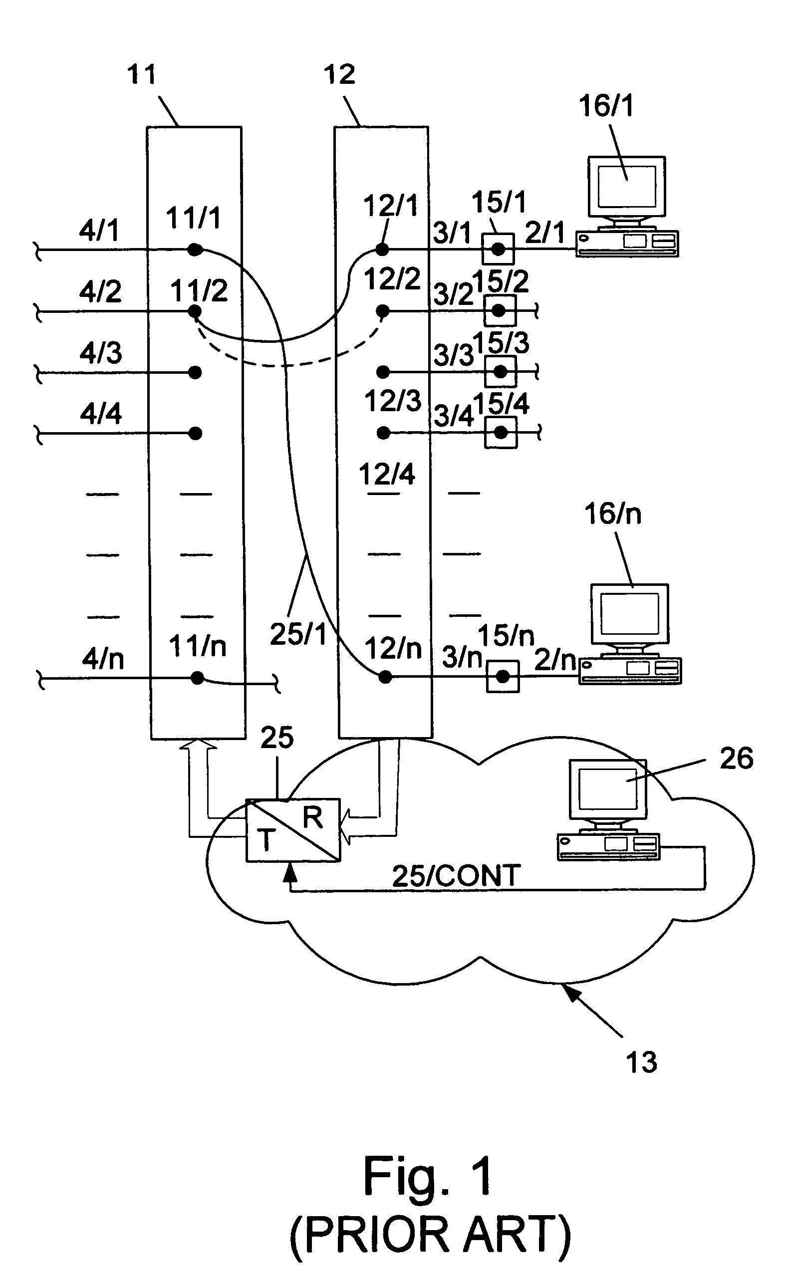
[0038]FIG. 1 schematically illustrates an exemplary basic scanning system for determining the connectivity map of connections between two patch panels (prior art). Patch panels 11 and 12 comprise data ports I to n. Static, data cables 4 / 1 to 4 / n are connected a first set of separate contacts 11 / 1 to 11 / n of panel 11. Said contacts 11 / 1 to 11 / n are connected to a second set of contacts 12 / 1 to 12 / n of panel 12 forming a cross-connection as indicated, for instance, by the connection of contact 11 / 1 to 12 / n, as shown in the drawing. Predetermined contacts in the first set of contacts 11 and predetermined contacts in the second set of contacts 12 are cross-connected, for allowing flexibility in connecting end-devices (e.g. computer 16 / n) to a corresponding remote end (not shown). Scanning system 13 typically comprises a scanner (25) and a computerized management unit (26) that synchronizes the operation of scanner 25 (i.e., via connection 25 / cont) and handles the content of a connectivi...


PUM

PropertyMeasurementUnit
distancesaaaaaaaaaa
lengthaaaaaaaaaa
electrical characteristicsaaaaaaaaaa

Abstract

Method and system for managing cabling rooms that include a plurality of communication panels, which are arranged closely to one another. Each cabling room has a plurality of patch panels, structurally connected to form vertical structures. An operator is automatically guided to a communication panel or a plurality of communication panels, in which changes are to be made to modify the connectivity status or to deal with connectivity problems that may arise for any reason. The system automatically indicates to an operator optimal ports that are available and optimal patch cords for connecting them, based on distances between ports and on the electrical characteristics of the electrical signals that it is intended to pass between the ports.

Description

RELATED APPLICATION[0001]The present application is a continuation of International Application No. PCT / IL04 / 000698 filed Jul. 29, 2004, which claims priority from Israeli Patent Application No. 157203, filed Jul. 31, 2003, the contents of which are here incorporated in their entirety; applicant claim the benefit of 35 USC §120.BACKGROUND OF THE INVENTION[0002]1. Field of the Invention[0003]The present invention relates to the field of cabling systems, More particularly, the present invention relates to a method for optimal management and control of interconnecting panels that are part of large scale cabling systems.[0004]2. Prior Art[0005]The term ‘managing’ (i.e., in connection with ‘management of cabling systems’, or ‘communication panels’, or ‘patch panel’) encompasses operations such as obtaining, and / or monitoring the connectivity status, or map, of a cabling system, and using the obtained data for guiding an operator through desirable cabling changes and indicating to the ope...

Claims


Application Information

Patent Timeline
Patent Type & Authority Patents(United States)
IPC IPC(8): G08B21/00G01R19/00B23P21/00G06F1/16G06FG08B25/00
CPCH04Q1/06H04Q1/136Y10T29/49004Y10T29/53
Inventor SHALTS, DAVIDGOVREEN-SEGAL, DAEL
Owner RIT TECHNOLOGIES
Why Eureka
Try Eureka