
Measurement system for determining six degrees of freedom of an object

a measurement system and object technology, applied in the field of metals, can solve the problems of not being able to achieve great accuracy in depth, and the method is relatively demanding

Active Publication Date: 2007-12-25
LEICA GEOSYSTEMS AG
View PDF11 Cites 143 Cited by
  • Summary
  • Abstract
  • Description
  • Claims
  • Application Information

AI Technical Summary

Benefits of technology

The invention is a measurement system that can determine the six degrees of freedom of an object using a reflector and an angle and distance measurement apparatus. The system includes an optically detectable addition element that allows for the determination of the rotation of the reflector or the object around the measurement beam axis. The measurement data used in the system includes the position and orientation of the angle and distance measurement apparatus, the reflector and the light-sensitive surface, the addition element, and the direction or line defined by the addition element. The system can be used in various applications such as guiding a robot arm or a vehicle along a predefined path. The technical effect of the invention is to provide a more accurate and reliable measurement system for determining the six degrees of freedom of an object.

Problems solved by technology

Since such photogrammetric evaluation of the six degrees of freedom is only suitable for moving objects if a plurality of simultaneously operating, advantageously stationarily arranged and calibrated cameras is provided, the method is relatively demanding, in particular regarding the data quantities which are to be handled.
If at least three light points are arranged on the object, and a calibrated camera is used, the data obtained from a single camera picture allows determination of the six degrees of freedom of the light point arrangement relative to the camera, wherein, however, no great accuracy can be achieved regarding depth, i.e. regarding the distance between the camera and the light point arrangement.

Method used


Image

  • Measurement system for determining six degrees of freedom of an object
  • Measurement system for determining six degrees of freedom of an object
  • Measurement system for determining six degrees of freedom of an object

Examples


Embodiment Construction

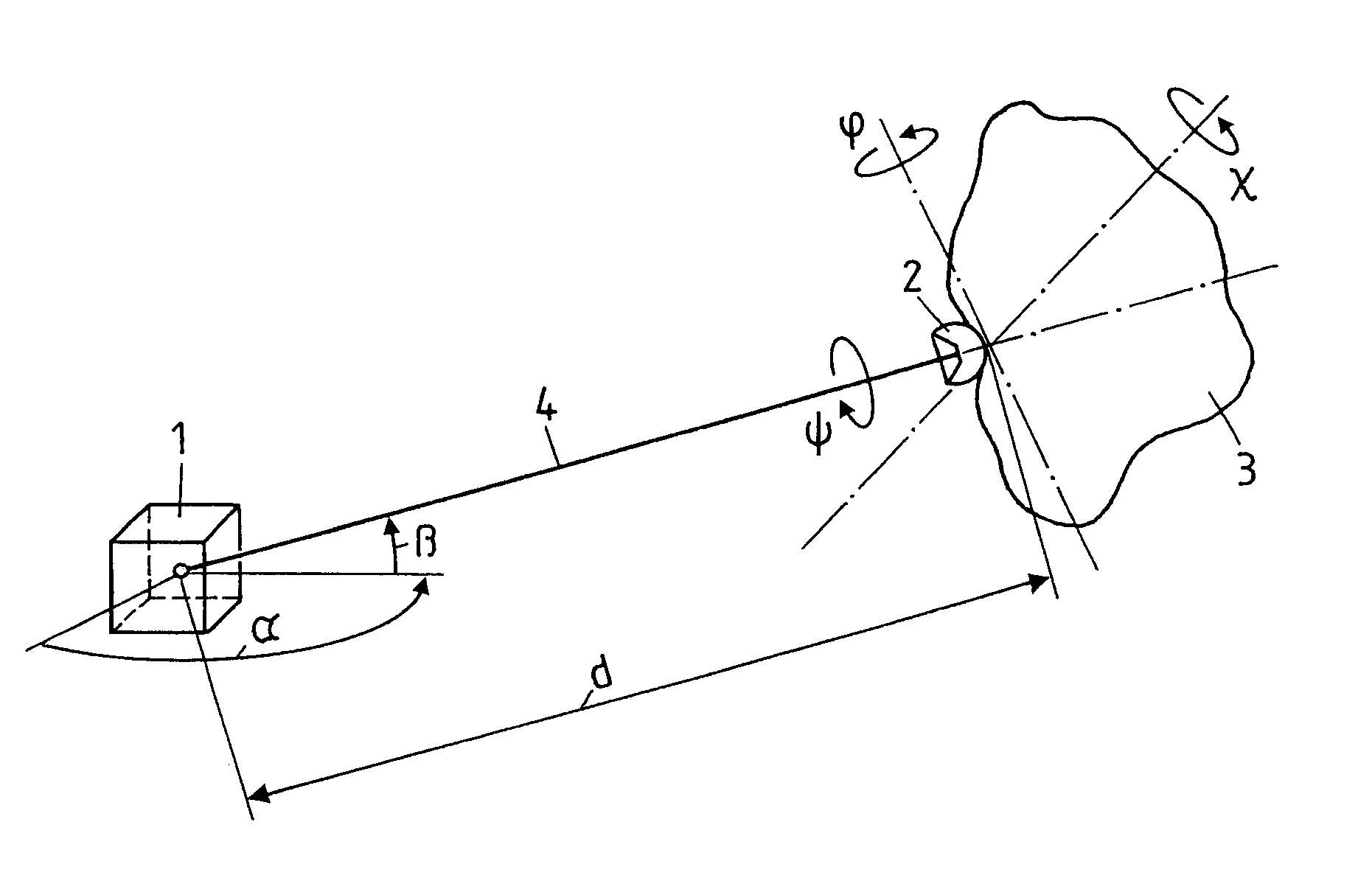
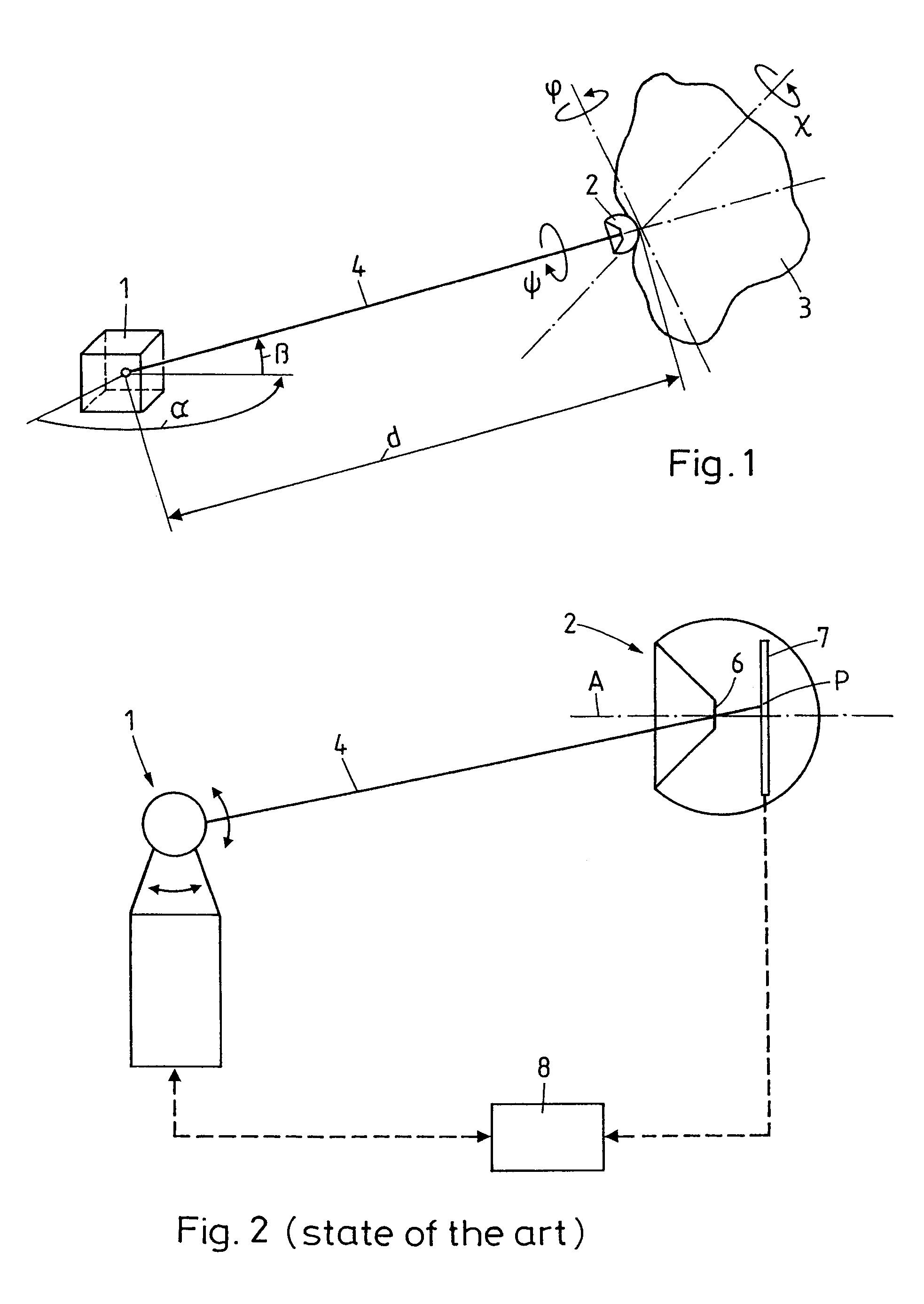
[0033]FIG. 1 shows the six degrees of freedom which are to be determined in the measurement system according to the invention. The angle and distance measurement apparatus 1, the reflector 2 arranged on the object 3 and the measurement beam 4 directed onto the reflector 2 by the angle and distance measurement apparatus 1 are shown schematically. The angle and distance measurement apparatus 1 measures the polar coordinates α, β and d of the reflector relative to a coordinate system (not shown) defined by the apparatus. The light-sensitive surface behind the reflector apex (not shown) measures the tilt angle φ and the yaw angle χ of the reflector relative to the measurement beam. The sixth degree of freedom is the roll angle ψ relative to the reflector axis or the measurement beam 4. All determined degrees of freedom can be transformed to further coordinate systems using known algorithms, if position and orientation of the coordinate system related to the angle and distance measuremen...


PUM


Abstract

A measurement system for determining six degrees of freedom (α, β, d, φ, χ, ψ) of a reflector (2) or of an object (3) on which the reflector is arranged, comprises an angle- and distance measurement apparatus (1), e.g. a laser tracker, operating with a laser beam as a measurement beam (4). The reflector (2) is designed for a parallel reflection of the measurement beam (4) and has an apical opening or surface (6), in a manner such that a part of the measurement beam (4) directed onto the reflector (2), passes through the apical opening or surface (6), and is incident on a light-sensitive surface (7) arranged behind the reflector apex. Five degrees of freedom (α, β, d, φ, χ) of the reflector (2) or the object (3) are computed from measurement data produced by the angle- and distance measurement apparatus (1) and by the light-sensitive surface (7).

Description

BACKGROUND OF THE INVENTION[0001]1. Field of the Invention[0002]The invention lies in the field of metrology and relates to a measurement system for determining six degrees of freedom of an object, in particular of a moving object, more specifically it serves for determining three position coordinates of a reference point of the object and three rotation angles (tilt, yaw- and roll angle) about three orthogonal axes which run through the object and which intersect, for example, in the reference point.[0003]2. Description of Related Art[0004]For determining the six degrees of freedom of an object, for example laser trackers, theodolites or theodolite-like measurement apparatus provided with distance meters are used, wherein direction and distance (polar coordinates) to a plurality of points marked with reflectors in known positions on the object are determined. From the measured coordinates of the points, the six degrees of freedom of the object relative to a predefined coordinate sy...

Claims


Application Information

Patent Timeline
Patent Type & Authority Patents(United States)
IPC IPC(8): G01B11/26
CPCG01S5/163G01S17/66G01S17/42
Inventor ZUMBRUNN, ROLANDMARKENDORF, ALBERTLOSER, RAIMUNDDOLD, JURGEN
Owner LEICA GEOSYSTEMS AG
Learn More