Distance determination in a scanned beam image capture device

a technology of distance determination and image capture device, which is applied in the field of distance determination in a scanned beam image capture device, can solve the problem that images may contain somewhat limited depth information, and achieve the effect of being easily identified and separated

Active Publication Date: 2007-12-25
UNIV OF WASHINGTON
View PDF65 Cites 70 Cited by
  • Summary
  • Abstract
  • Description
  • Claims
  • Application Information

AI Technical Summary

Benefits of technology

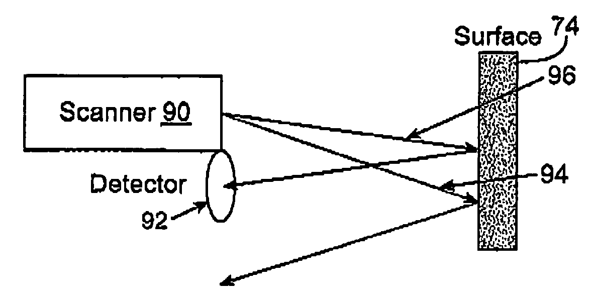
[0007]The present invention provides methods, systems, and devices for determining spatial relationships between a probe and a target surface. Embodiments of the invention will take advantage of specular reflections from the target surface. Unlike the diffuse backscatter reflections upon which much of the image in a scanned beam device is typically based, these specular reflections typically vary dramatically with small changes in angle between the scanning beam and the target surface. As the geometry of the beam scanner and light detector of the probe are known, and as the angle of the light beam projected from the scanner is often used for accurately generating an image, the pattern of spectral light reflected from the target surface back to the detector(s) may allow the distance between the probe and the target surface, and / or the angular relationship between the probe and the target surface, to be calculated. Conveniently, the specular reflections are typically readily identified and separated from the diffuse reflected light from which an image is primarily formed, as the specular reflections will often be significantly brighter than the diffuse reflected light. Hence, the spatial relationships can be determined without adding significant mechanical complexity or bulk to scanning beam imaging devices such as the new scanning fiber endoscopes.
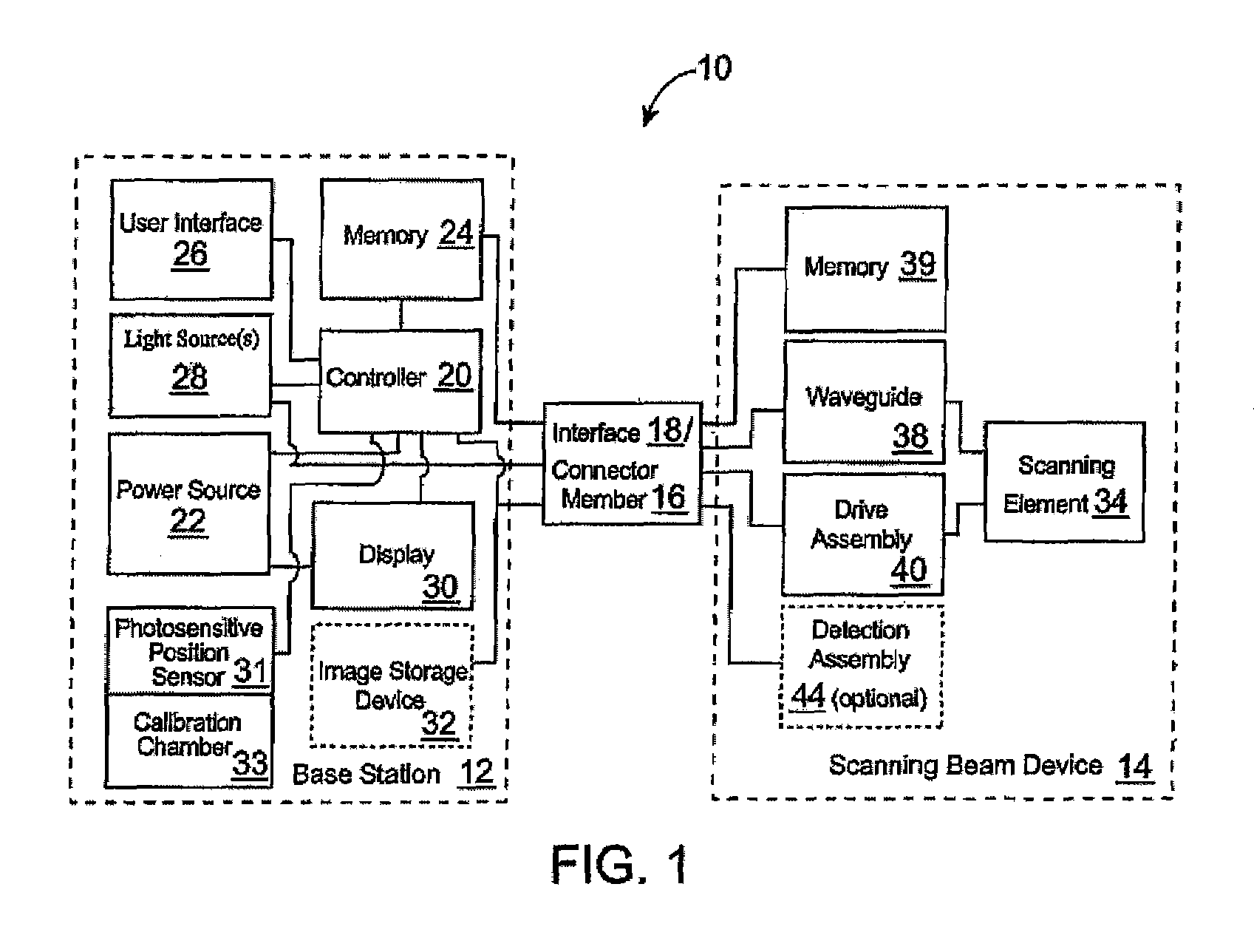
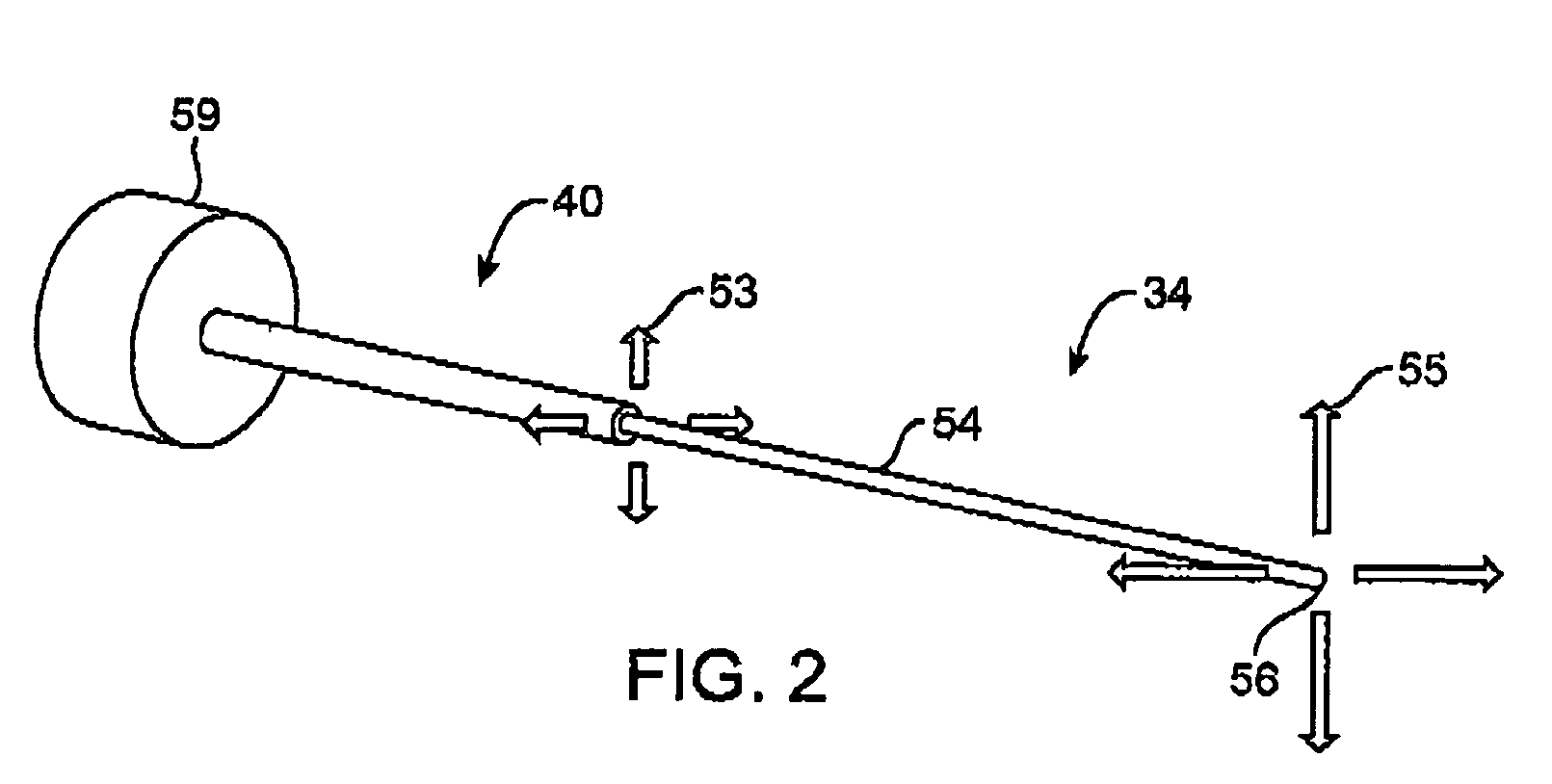
[0009]The probe will often comprise an endoscope, the surface often comprising a tissue surface within a patient body. The beam may be oscillated by vibrating an optical fiber with a two-dimensional scan (such as a spiral or the like), and the probe will often transmit image signals for imaging of the tissue surface in response to diffuse reflection of the light beam from the tissue surface. Both the diffuse light and specular light may be detected by the detector of the probe. Specular image signals may be separated from display image signals using a difference in brightness between these two different forms of reflected light. The spatial relationship may be determined using these separated specular image signals, such as by analyzing a centroid of a specular reflection, a pattern of specular reflections received by a plurality of detectors, a shape of a specular reflection, or the like. As the specular reflection may be located in a relatively small portion of the overall imaging field of view, an angular scan magnitude may be reduced when measuring the specular reflection so as to enhance measurement resolution.
[0010]Typically, the distance or angle will be determined at least in part from an angle of the oscillating beam when the specular reflection is sensed. The beam will be oscillated with a scanner, and the distance between the probe and the surface may be determined, for example, using a scanner / detector distance between, for example, a center of the scanner and the detector. In some embodiments, the specular reflection may be sensed with a plurality of light detectors of the probe, so that a pattern of spectral reflections from the surface are determined. The distance may be determined in response to a spectral reflection pattern size, and / or in response to a single spectral reflection from an associated single detector, so that a plurality of distances may optionally be measured when using multiple detectors. Where the detectors are at different distances from the center of the scan, additional information regarding the angle and / or geometry of the target surface can be identified. Similarly, when the angle of the surface is determined relative to the probe, the angle may be determined at least in part from a shape of an individual specular reflection received at a single detector, a shape of a pattern of spectral reflections received by a plurality of detectors, a size of an individual spectral reflection or pattern of spectral reflections, or the like. By measuring the angle of the surface relative to the probe at a plurality of locations within a field of view of the probe (for example, by using a probe having a plurality of detectors, or by moving at least a portion of the probe between two different measurements), a map of the target surface geometry may be generated. In some embodiments, the entire probe may move, with the system identifying one or more datum locations in the images before and after the movement so as to accurately combine the two separate measurements.
[0011]While generally described as being based on an image, it should be understood that a plurality of spectral reflection images may be combined (such as by averaging the images) so as to enhance image accuracy. Individual diffuse and / or spectral images may be generated at a rate of at least 1 frame per second, often being 15-30 frames per second.

Problems solved by technology

Scanning beam systems may fill the needs in some or all of these applications, although challenges remain in providing the desired optical characteristics at a reasonable cost.
Hence, these images may contain somewhat limited depth information.

Method used


Image

  • Distance determination in a scanned beam image capture device
  • Distance determination in a scanned beam image capture device
  • Distance determination in a scanned beam image capture device

Examples


Embodiment Construction

[0029]The present invention generally provides improved scanned beam devices, systems, and methods. The improved scanned beam techniques will often provide spatial information (such as separation distance, an angle, or even a contour map) of a target surface, typically using spectral reflections from the target surface.

[0030]The scanning beam systems of the present invention will often include a scanning beam device or probe and a base station for controlling the scanning beam device. The scanning beam devices may take on a variety of forms, but will typically comprise a flexible or rigid endoscope, catheter, fiberscope, microscope, boroscope, or the like. The scanning beam devices may have a limited life (e.g., being disposable) or may be multiple-use devices. If the device is for medical use, the scanning beam devices will generally be sterile, either being sterilizable or being provided in hermetically sealed packages for use.

[0031]The scanning beam devices or probes will often i...


PUM


Abstract

Methods, systems, and devices can determine spatial relationships between a probe and a target surface. Specular reflections from the target surface vary dramatically with small changes in angle between the scanning beam and the target surface, and as the geometry of the beam scanner and light detector of the probe are often known, and as the angle of the light beam projected from a scanner for accurately generating an image, the pattern of spectral light reflected from the light beam directly back to the detector allows the distance between the probe and the target surface, and / or the angular relationship between the probe and the target surface, to be calculated.

Description

BACKGROUND OF THE INVENTION[0001]The present invention is generally related to scanning beam devices, systems, and methods. More specifically, the present invention can provide distance measurements, angle measurements, and / or other geometrical relationships between a scanned beam device and a surface, such as between a scanning fiber endoscope and an internal tissue, typically by identifying specular reflection signals from the surface.[0002]There is a growing market for micro-optical devices, and particularly for small image acquisition systems (e.g., cameras). Micro-optical systems having appropriate optical characteristics and size may find use in a variety of applications including minimally invasive medical imaging (and particularly in flexible endoscopes), in surveillance, in industrial inspection and repair, in machine and robotic vision systems, in micro-barcode scanners, and the like. Scanning beam systems may fill the needs in some or all of these applications, although c...

Claims


Application Information

Patent Timeline
Patent Type & Authority Patents(United States)
IPC IPC(8): A61B19/00G01B11/26
CPCA61B5/0084A61B5/1076G02B26/10G01B11/14G01B11/26G01B11/026A61B5/0062
Inventor JOHNSTON, RICHARD S.
Owner UNIV OF WASHINGTON
Why Eureka
Try Eureka