Communications system and method

a communication system and communication technology, applied in the field of communication system and method, can solve the problems of limiting the operational benefits of a switched approach, the economic cost of optical fiber cables, etc., and achieve the effect of fine granularity

Active Publication Date: 2007-12-25
NEXTG NETWORKS INC
View PDF8 Cites 167 Cited by
  • Summary
  • Abstract
  • Description
  • Claims
  • Application Information

AI Technical Summary

Benefits of technology

[0005]The present invention provides system architecture that gives the operational benefits of a switched-DAS, without the problems caused by fiber availability, by describing a network containing switched wireless links. Furthermore, the present invention describes a system architecture that incorporates distributed switching within remote hubs in order to provide fine granularity in allocating services to antennas.
[0007]The base stations are usually grouped together in a convenient central location, sometimes known as a base station hotel. The radio signals from the centrally located base stations are therefore distributed to many remote antennas using an architecture containing main hubs and remote hubs. The switch matrix, under software control, is able to change the network configuration, i.e., to change which signals from which base stations go to which antenna cluster. This is important in many situations, for example, to be able to move network capacity from under-utilized coverage areas to relieve congestion in over-utilized coverage areas. An example of this situation is the sports stadium scenario, where capacity requirements are very low apart from when an event is taking place. The switch matrix would mean that a dedicated base station is not necessary for the sports stadium, leading to a saving in capital equipment cost. There are many other situations where the switch matrix gives both capital and operational cost savings; these are described in Wake and Beacham cited above.

Problems solved by technology

However, there are situations where optical fiber cables are not available at economic cost at places where they are required.
However, the fixed configuration described by Chu limits the operational benefits of a switched approach.

Method used


Image

  • Communications system and method
  • Communications system and method
  • Communications system and method

Examples


Embodiment Construction

[0016]In the following description of embodiments, reference is made to accompanying drawings which form a part hereof and in which is shown by way of illustration specific embodiments in which the invention may be practiced. It is to be understood that other embodiments may be utilized and structural changes may be made without departing from the scope of the preferred embodiments of the present invention.

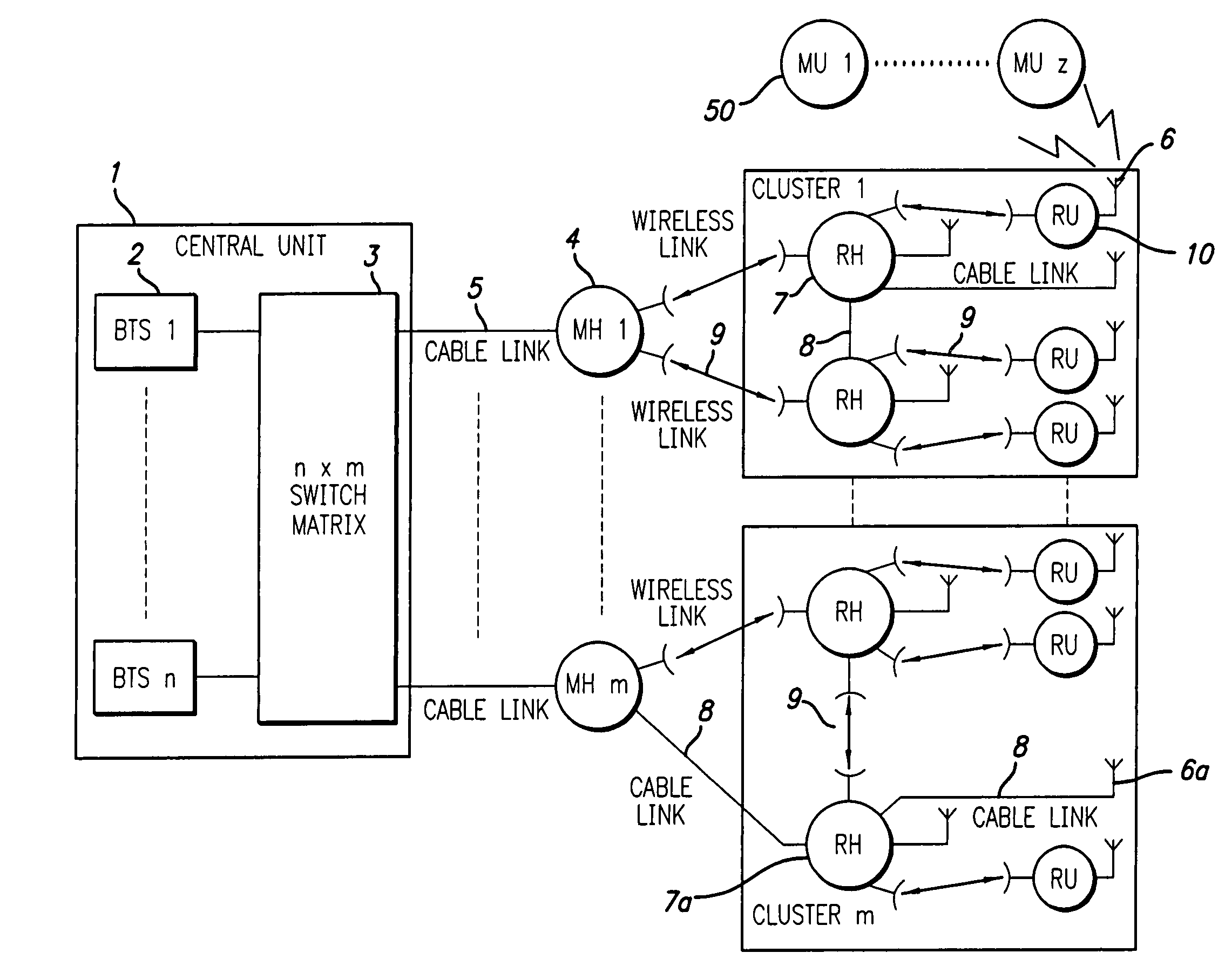
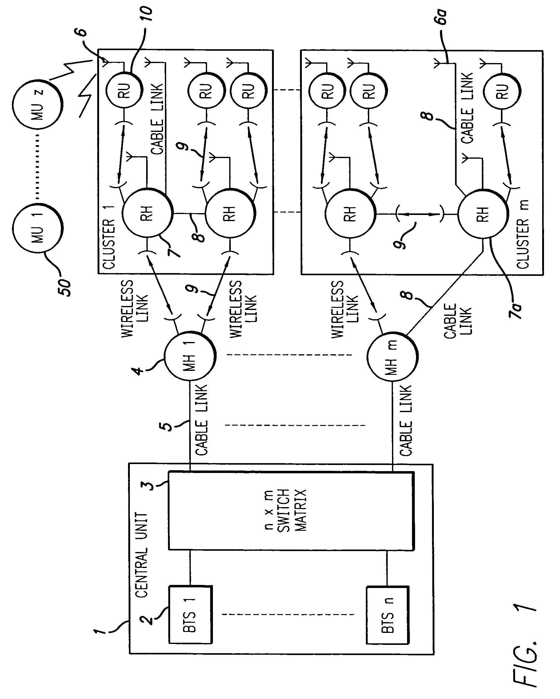
[0017]FIG. 1 is a schematic representation of a signal distribution system of the present invention. The central unit 1 comprises a number of base stations 2 and a n×m switch matrix 3. The base station output ports are connected to the input ports of the switch matrix. The output ports of the switch matrix are connected to a number of main hubs 4 using cables 5.

[0018]In one example, the base stations could be located within an equipment room inside a building and the main hubs could be located on the top of the building. The cables would either be optical fiber or coaxial dependin...


PUM


Abstract

A signal distribution system for distributing signals, such as for outdoor wireless networks, comprises a number of remote hubs, each of which can direct wireless signals to a number of antennas. The antennas are used to provide wireless service to the service users, such as mobile units, within their geographic coverage area. The remote hubs are connected to main hubs, which are usually located centrally. Each main hub can support a number of remote hubs. The main hubs are connected to a number of base stations (again usually located centrally) in a flexible and re-configurable manner using a switch matrix. Some remote hubs may also include switched matrices for a further level of signal routing.

Description

BACKGROUND OF THE INVENTION[0001]The present invention relates to a communications system and method and, more particularly, to a signal distribution system and method for switching and connecting cells in a communications network.[0002]The use of a switching matrix for wireless communications systems based on distributed antennas is disclosed by Motley et al. in U.S. Pat. No. 5,682,256. Motley et al. uses a switching matrix to interconnect a number of base stations on the input ports to a number of distributed antennas on the output ports. The switch matrix allows any combination of inputs to be connected to any combination of outputs so that base stations can be connected to antennas in a very flexible manner. This allows wireless services such as cellular radio to be delivered to users with significant cost savings for network operators. The benefits of using a switched distributed antenna system are outlined for example in a paper by Wake and Beacham, “Radio over fiber networks ...

Claims


Application Information

Patent Timeline
Patent Type & Authority Patents(United States)
IPC IPC(8): H04B1/38H04W88/08
CPCH04W88/085
Inventor WAKE, DAVIDBEACHAM, KEITH
Owner NEXTG NETWORKS INC
Why Eureka
Try Eureka