Panel clip assembly for use with roof or wall panels

a technology for roof or wall panels and clip assemblies, which is applied in haberdashery, ceilings, walls, etc., can solve the problems of thermal forces (expansion and contraction) on the support and joining of panels by clip assemblies, damage to panels or clip assemblies, and undesirable noise and wear, so as to reduce wear and noise.

Inactive Publication Date: 2008-01-01
EXTECH EXTERIOR TECH
View PDF64 Cites 65 Cited by
  • Summary
  • Abstract
  • Description
  • Claims
  • Application Information

AI Technical Summary

Benefits of technology

[0009]It is therefore an object of the present invention to address the above shortcomings of the prior art. In particular, it is an object of the present invention to allow movement of the panels. It is a further object of the present invention to allow for panel movements in the planes of the panels that are both longitudinal and transverse to the seam formed by adjoining panels and typically arising from thermal expansion or contraction of the panels. It is also an object of the present invention to reduce wear and noise resulting from frictional movement of roof panels against a substrate or clip assembly.
[0010]In one aspect of the present invention, the clip assembly secures standing seam skylight or roofing panels to a substrate and allows for longitudinal movement by the panels, while eliminating or reducing frictional noises and wear. The clip assembly may also be used with wall panel systems.

Problems solved by technology

As noted in this prior art, a continuing problem has existed concerning the impact of thermal forces (expansion and contraction) on panels supported and joined together by clip assemblies.
By way of example, if clip assemblies are too rigid, damage may occur to the panels or clip assemblies during thermal expansion or contraction.
In addition, undesirable noises and wear are caused by frictional panel movement resulting from thermal and other forces, i.e. panels rubbing against the clip assembly, against the fasteners that hold the clip assembly, and against the substrates.
Existing clip assemblies continue to experience problems from thermal forces, however.
In particular, existing clip assemblies are too rigid in respect to, and do not adequately address, thermal forces that are applied perpendicular to panel seams (and perpendicular to the sliding movement allowed for in the clip assemblies described above).
Thus, wear and damage problems from such forces continue to exist.
In addition, unwanted frictional noises have not been satisfactorily eliminated or reduced.
No existing clip assembly addresses the need for an assembly that includes these features and that allows for and addresses various ranges of movement experienced by panels and that also eliminates or reduces corresponding frictional noises and wear.

Method used


Image

  • Panel clip assembly for use with roof or wall panels
  • Panel clip assembly for use with roof or wall panels
  • Panel clip assembly for use with roof or wall panels

Examples


Embodiment Construction

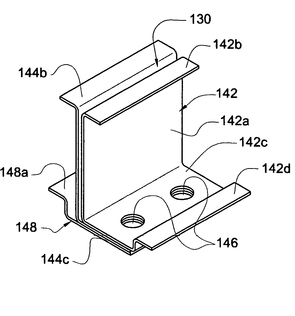
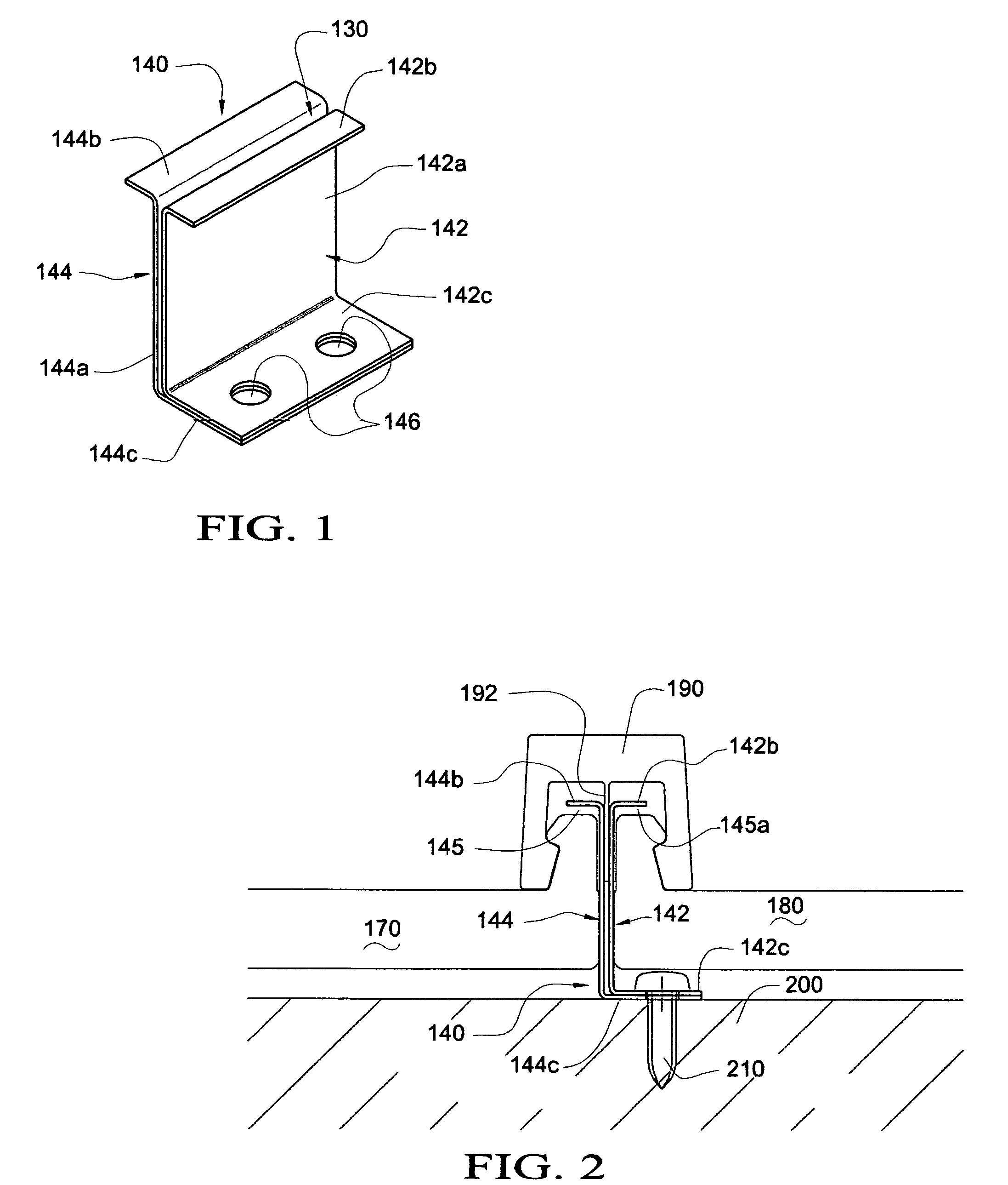
[0027]FIG. 1 in an isometric view of a preferred embodiment of the clip assembly of the present invention. In this embodiment, the clip assembly is generally designated by reference numeral 140. The clip assembly 140 includes a first clip member 142 and a second clip member 144. The first clip member is substantially a “C” shaped clip member having an upright body portion 142a and respective upper and lower extending horizontal flanges 142b and 142c. The lower horizontal flange 142c includes openings or holes 146 designed to accommodate a fastening member. The second clip member 144 is substantially an “S” shaped clip member having an upright body portion 144a and upper and lower extending horizontal flanges 144b and 144c, where the upper and lower extending horizontal flanges 144b and 144c extend in opposite directions. The lower horizontal extending flange 144c further includes holes 146 corresponding to and aligned with the holes 146 of the horizontal extending flange 142c.

[0028...


PUM


Abstract

A clip assembly secures standing seam skylight or roofing panels to substrates and allows for a full range of movements by the panels while eliminating or reducing frictional noises. The clip assembly may also be used with wall panel systems. The clip assembly includes a first clip member and a second clip member each having an upright member and an upper flange member and a lower flange member extending therefrom. The assembly further includes a gap formed between the upright member of the first clip member and the upright member of the second clip member. In one aspect the clip assembly includes a base which allows the assembly to slide.

Description

CROSS REFERENCE TO RELATED APPLICATIONS[0001]This application is related to U.S. Provisional Application Ser. No. 60 / 424,706 filed Nov. 8, 2002.BACKGROUND OF THE INVENTION[0002]1. Field of the Invention[0003]The present invention generally relates to a panel clip assembly and more particularly, to a panel clip assembly for use with skylight, roof or wall panels having improved strength, improved noise reduction and improved allowance for longitudinal and transverse panel movement in response to thermal expansion and contraction of the panels.[0004]2. Description of the Prior Art[0005]It is well known to secure standing seam roof and wall panels, including translucent panels, to purlin or girt substrates using hidden clips and related clip assemblies. Examples of various of these clip assemblies are shown in U.S. Pat. Nos. 4,184,299, 4,193,247, 4,361,998, 4,495,743, 4,543,760, 4,575,983, 5,001,882, 5,181,360, 5,222,341, 5,363,624, 5,606,838 and 6,164,024. As noted in this prior art, ...

Claims


Application Information

Patent Timeline
Patent Type & Authority Patents(United States)
IPC IPC(8): E04D1/36E04B2/00E04D3/361E04D3/366
CPCE04D3/361E04D3/366E04D3/363E04D2003/285Y10T24/44017Y10T403/32229E04D2003/3615
Inventor VOEGELE, JR., WILLIAM P.
Owner EXTECH EXTERIOR TECH
Why Eureka
Try Eureka