Kneebag and occupant leg protection system

a technology for occupant leg protection and kneebags, which is applied in the direction of vehicular safety arrangements, pedestrian/occupant safety arrangements, vehicle components, etc., can solve the problems of large kneebags and difficulty in disposing of occupant leg protection systems in the region

Active Publication Date: 2008-01-01
JOYSON SAFETY SYST JAPAN GK
View PDF14 Cites 58 Cited by
  • Summary
  • Abstract
  • Description
  • Claims
  • Application Information

AI Technical Summary

Benefits of technology

[0011]In the kneebag and the occupant leg protection system according to the present invention, the inflated kneebag has the thickness at the upper portion larger than that at the middle portion of the kneebag in the vertical direction. In other words, the thickness of the kneebag is smaller at the middle portion of the kneebag in the vertical direction than the upper portion of the kneebag. Accordingly, when the kneebag is inflated, the middle portion of the kneebag in the vertical direction is quickly inflated upwardly from below, and the upper portion of the kneebag is deployed quickly in front of the occupant knees without a high-output inflator. The upper portion of the inflated kneebag has a sufficient thickness across a lateral width thereof.

Problems solved by technology

Accordingly, it is sometimes difficult to dispose an occupant leg protection system in the region.
However, in such a structure, it is necessary to inflate the kneebag upwardly from below over a relatively long distance from a height lower than the occupant knees to a height facing the knees, thereby making the kneebag large.

Method used


Image

  • Kneebag and occupant leg protection system
  • Kneebag and occupant leg protection system
  • Kneebag and occupant leg protection system

Examples


Embodiment Construction

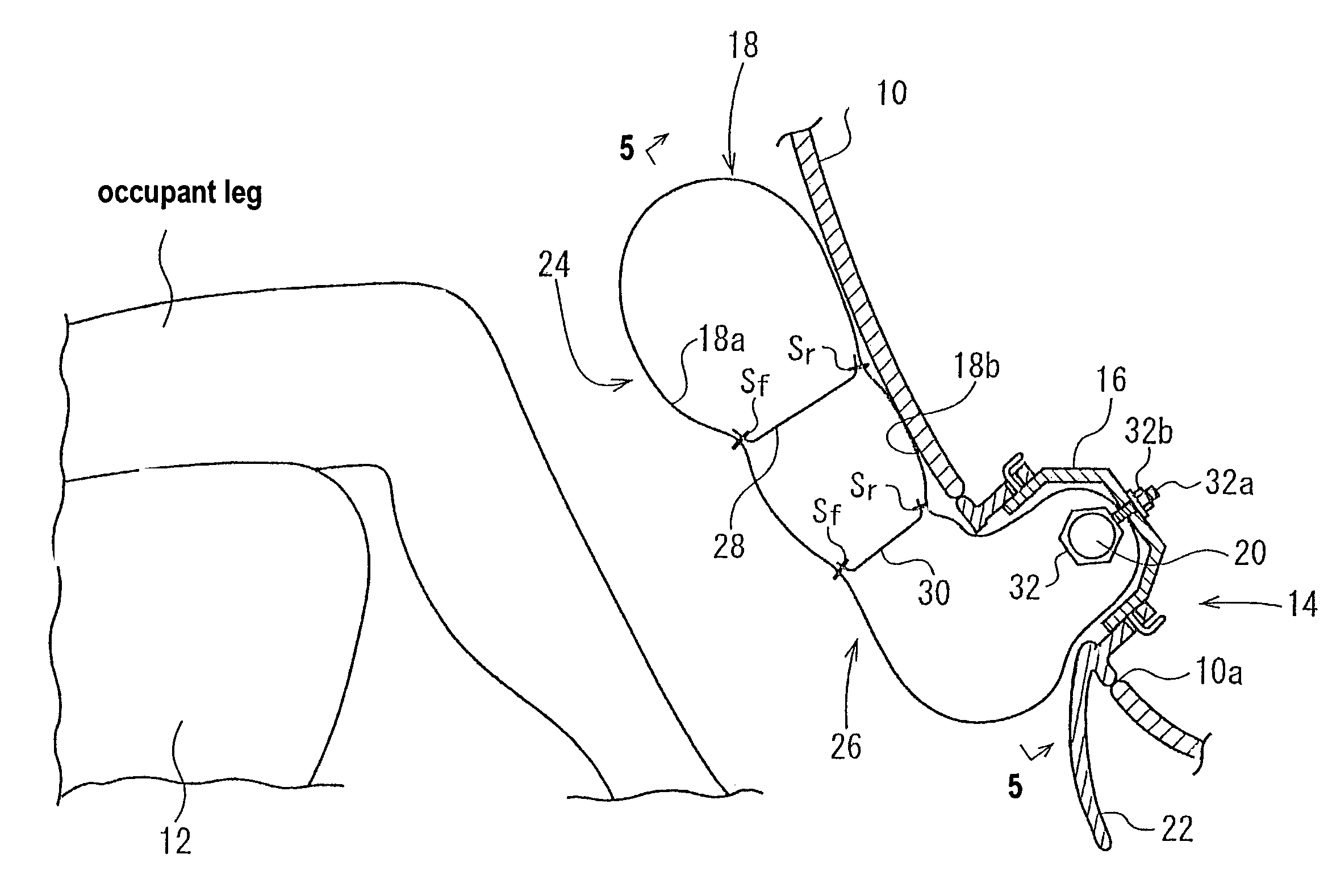
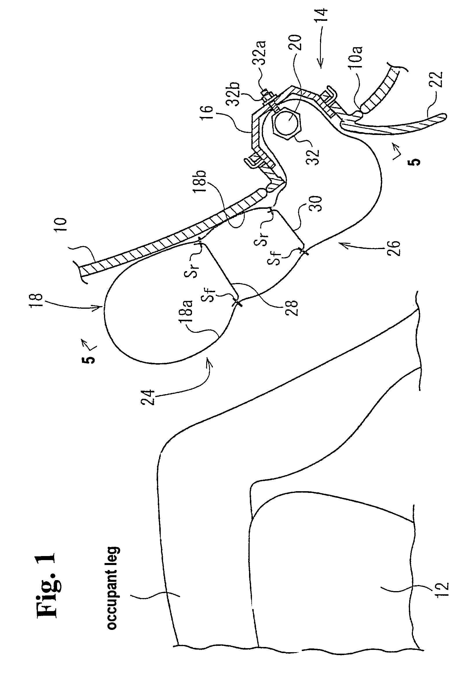
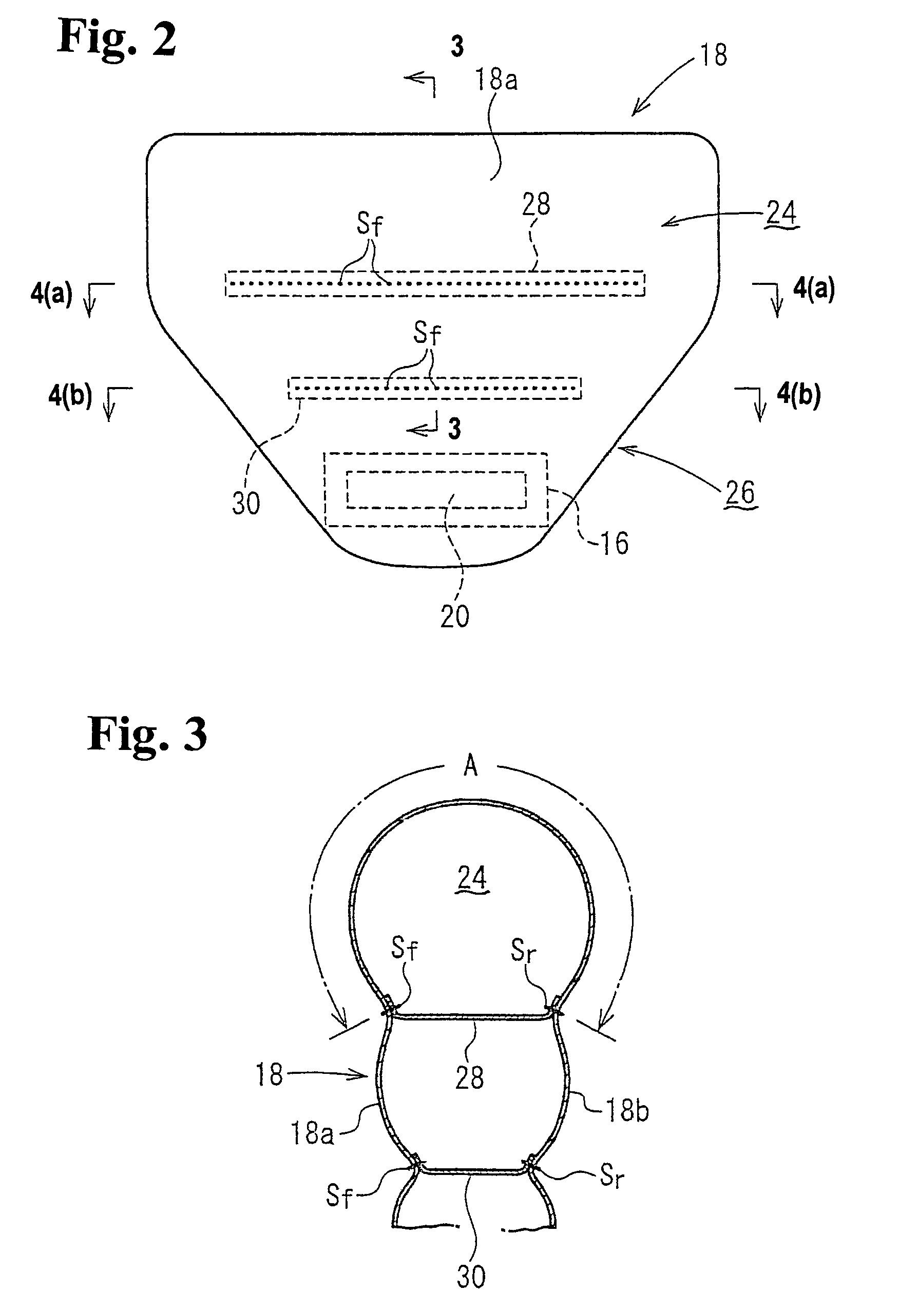
[0019]Hereunder, embodiments of the present invention will be described with reference to the accompanying drawings. FIG. 1 is a cross-sectional view of the vicinity in front of a vehicle seat showing an inflated state of a kneebag according to an embodiment of the present invention. FIG. 2 is a front view of the kneebag in an inflated state. FIG. 3 is a cross-sectional view taken along line 3-3 in FIG. 2. FIGS. 4(a) and 4(b) are cross-sectional views taken along line 4(a)-4(a) and line 4(b)-4(b) in FIG. 2, respectively. FIG. 5 is a cross-sectional view taken along line 5-5 in FIG. 1. In the following description, a lateral direction is a direction along a width of a vehicle.

[0020]An occupant leg protection system 14 is mounted to an interior panel 10 in front of a seat 12. The occupant leg protection system 14 includes a container-like retainer 16 with an open front surface (surface adjacent to an occupant), a kneebag 18 connected to the retainer 16, and an inflator (gas generator)...


PUM


Abstract

A kneebag is arranged to be inflated upwardly from below in front of legs of an occupant in a vehicle. In an inflated state, the kneebag has a thickness at an upper portion thereof larger than that of a middle portion in a vertical direction of the kneebag except left and right side portions thereof.

Description

BACKGROUND OF THE INVENTION AND RELATED ART STATEMENT[0001]The present invention relates to a knee airbag or kneebag for restraining knees of an occupant so that a lower body of the occupant does not move toward a front side of a vehicle to prevent lower legs of the occupant from striking against an interior panel in front of a seat in an event of a collision of the vehicle, and also relates to an occupant leg protection system including the kneebag.[0002]As an occupant leg protection system for protecting lower legs of an occupant from striking against an interior panel in front of a seat and from receiving a large load in an event of a head-on collision of a high-speed vehicle such as a car, there has been a system including a kneebag to be inflated in front of the occupant legs and an inflator (gas generator) for inflating the kneebag.[0003]Japanese Patent Publication (Kokai) No. 11-321539 has disclosed an occupant leg protection system in which a kneebag is inflated in a region ...

Claims


Application Information

Patent Timeline
Patent Type & Authority Patents(United States)
IPC IPC(8): B60R21/231B60R21/16B60R21/02B60R21/20B60R21/206B60R21/233B60R21/2338
CPCB60R21/233B60R21/2338B60R2021/23169B60R2021/23382
Inventor KUMAGAI, MASAYOSHIABE, KAZUHIROKAWAUCHIMARU, MASATOSHI
Owner JOYSON SAFETY SYST JAPAN GK
Why Eureka
Try Eureka