Backlight system

a backlight system and backlight technology, applied in static indicating devices, lighting and heating apparatuses, instruments, etc., can solve the problems of reducing the power efficiency of single-side power supply inverter devices, shortening the life of lamps, etc., to improve brightness uniformity, enhance power supply system efficiency, and prolong lamp life

Inactive Publication Date: 2008-01-01
NEC MITSUBISHI ELECTRIC VISUAL SYST
View PDF40 Cites 18 Cited by
  • Summary
  • Abstract
  • Description
  • Claims
  • Application Information

AI Technical Summary

Benefits of technology

[0016]An object of the present invention is to provide a backlight system that is capable of lengthening lamp lifetime through uniform temperature distribution, improving brightness uniformity, enhancing power-supply system efficiency, and ensuring safety through lowered voltages.

Problems solved by technology

Such temperature difference between the electrodes 7 and 9 of straight CCFL lamps 1 causes mercury to concentrate in the lower-temperature portion and then sputtering occurs at mercury-lacking terminals, which shortens the life of lamps.
This leads to a reduction in power efficiency of the single-side power-supply type inverter device 5.
These problems arise also with such U-shaped tubes as are disclosed in the two Patent Documents cited above.

Method used


Image

  • Backlight system
  • Backlight system
  • Backlight system

Examples


Embodiment Construction

[0048]First Preferred Embodiment

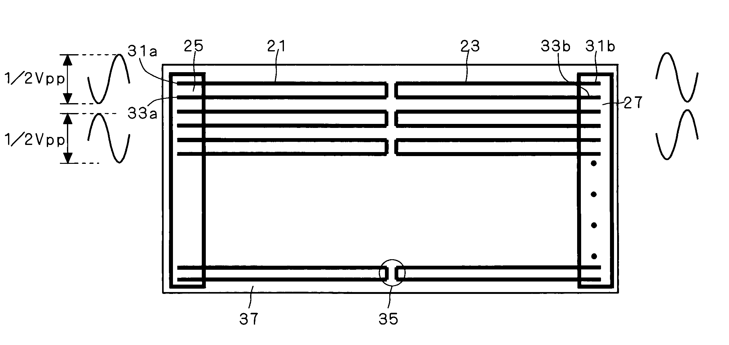
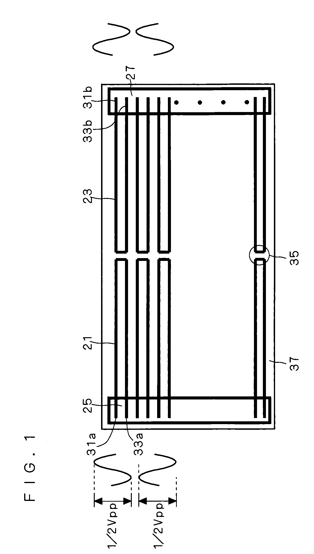
[0049]FIG. 1 is a schematic diagram showing the backlight system according to a first preferred embodiment of the invention. This preferred embodiment illustrates as an example an electronic display device whose display screen is wider than it is high.

[0050]This backlight system is used for rear illumination in a large-area electronic display device such as a large-sized liquid-crystal display. As shown in FIG. 1, a plurality of bent tubes 21 and 23, or U-shaped CCFL lamps, are arranged as linear lamps; in particular, the area is divided into left and right halves where bent tubes 21 and 23 are separately disposed opposite to each other. The bent tubes 21 on the left are supplied with power from a first floating power-supply type inverter device 25 provided at the left end and the bent tubes 23 on the right are supplied with power from a second floating power-supply type inverter device 27 provided at the right end.

[0051]Each bent tube 21 or 23 has po...


PUM

PropertyMeasurementUnit
lengthaaaaaaaaaa
aspect ratioaaaaaaaaaa

Abstract

A backlight system for use with a liquid-crystal display provides longer lamp lifetime through uniform temperature distribution, offers improved brightness uniformity and enhanced power-supply system efficiency, and ensures safety through lowered voltages. Linear lamps (21, 23) are divided into left and right approximately in the middle. The distance that heat travels is therefore shorter than when linear lamps have a length extending throughout the horizontal direction, which enables more uniform temperature distribution on the entire screen and lengthens the lifetime of linear lamps (21, 23). Furthermore, stray current is halved to achieve uniform brightness and enhanced inverter efficiency and safety can be easily ensured through lowered voltages.

Description

[0001]This Nonprovisional application claims priority under 35 U.S.C. § 119(a) on U.S. patent application Ser. No. 2003-173445 filed in CHINA on Jun. 18, 2003, the entire contents of which are hereby incorporated by reference.BACKGROUND OF THE INVENTION[0002]1. Field of the Invention[0003]The present invention relates to backlight systems for use in electronic display devices having light sources, such as liquid-crystal displays, and particularly to a backlight system with light-source arrangement, connection, power feeding, and uniformities in light emission from the display surface.[0004]2. Description of the Background Art[0005]FIG. 19 is a schematic diagram showing an example of a conventional backlight system for use in an electronic display device having a light source, e.g. a liquid-crystal display. In this backlight system, a plurality of parallel-arranged straight CCFL (Cold Cathode Fluorescent Tube) lamps 1, or linear lamps, are accommodated in a lamp house 3, with a singl...

Claims


Application Information

Patent Timeline
Patent Type & Authority Patents(United States)
IPC IPC(8): F21S4/00G02F1/13357F21S2/00F21V7/04F21V11/00F21Y103/37G02B6/00G02F1/133G02F1/1335
CPCG02F1/133604G02B6/0071B05B7/0018B05B7/0093B05B7/02B05B12/002
Inventor WAKABAYASHI, TOSHITSUGU
Owner NEC MITSUBISHI ELECTRIC VISUAL SYST
Why Eureka
Try Eureka