
Method and apparatus for controlling slurry distribution

a technology of slurry and distribution method, which is applied in the manufacture of grinding machines, manufacturing tools, and base layer manufacturing, etc., can solve the problems of defective ic devices, unresolved challenges, and slurry consumption, and achieve the effect of improving the control of chemical composition and addressing the loss of chemical reactivity

Inactive Publication Date: 2008-01-01
SPEEDFAM IPEC
View PDF20 Cites 13 Cited by
  • Summary
  • Abstract
  • Description
  • Claims
  • Application Information

AI Technical Summary

Benefits of technology

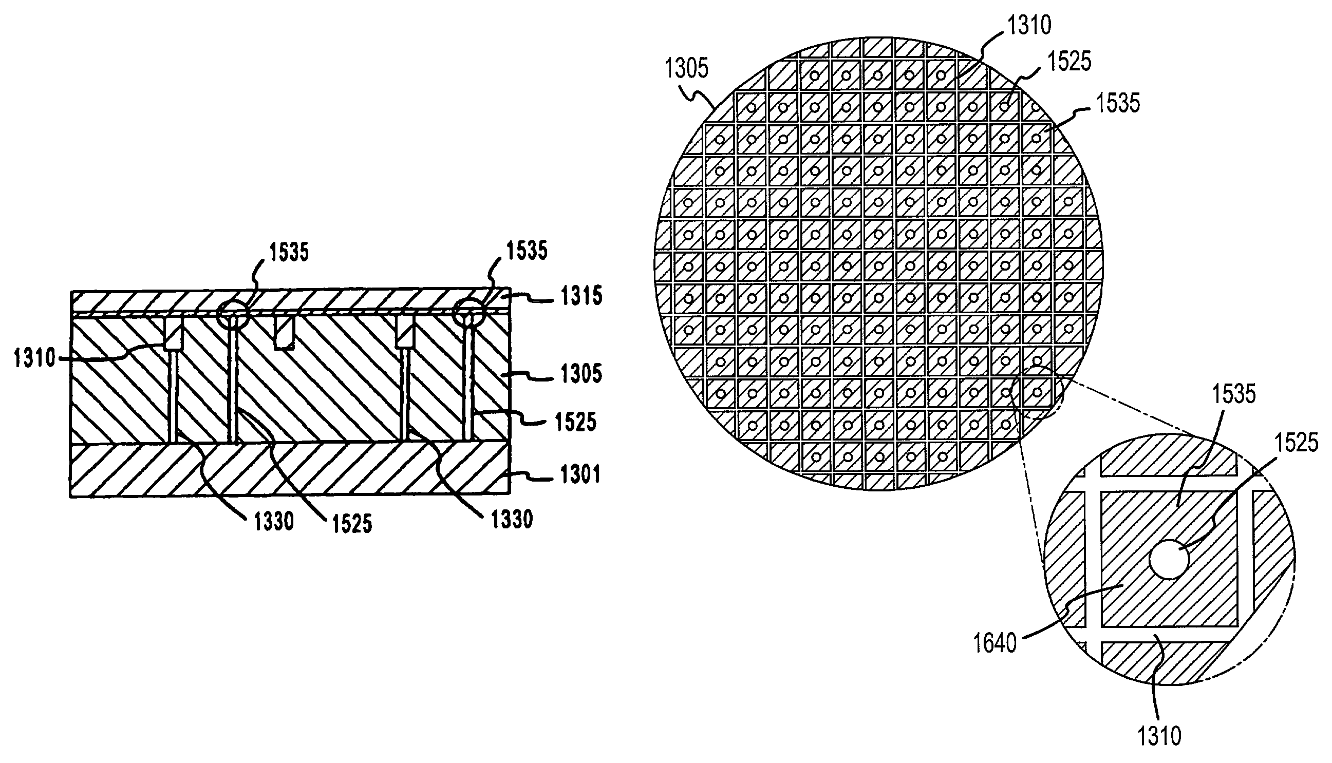
[0025]In accordance with various aspects of the present invention, the invention provides a method and apparatus for ‘through-the-pad’ delivery of slurry polishing agents distributed from multiple sources to the land areas of a polishing pad in order to overcome many of the shortcomings of the prior art, such as, uneven and / or nonuniform processing of workpiece surfaces. The present invention further provides for improved control of the chemical composition of the slurry to address loss of chemical reactivity of the slurry during the polishing cycle due to, for example: (1) chemical leaching of material away from the polished substrate; (2) stress corrosion; and / or (3) cross reactions that may occur between chemically reactive slurry components.
[0026]In accordance with one aspect of the present invention, slurry delivery channels are configured to distribute polishing slurry through the land areas of a polishing pad whereby slurry is introduced directly to the pad-wafer interface. Additionally, various groove modifications to the polishing surface of the pad are disclosed for: (1) improved control of the retention time experienced by the slurry at the pad-wafer interface; and (2) to reduce the anisotropy of land-area slurry retention at peripheral regions of the polishing pad caused by conventional X-Y groove patterns.
[0028]In accordance with a further aspect of the present invention, the number of slurry delivery channels (both in the land areas and in the X-Y grooves), and the flow rates to the same, are optimized to provide means for selectively controlling slurry chemistry at the pad-wafer interface during a polishing cycle. Moreover, various non-reactive slurry components may be independently distributed to various delivery channels, whereby the non-reactive slurry components experience ‘point-of-use’ mixing to generate a locally reactive slurry compound or admixture, wherein the appearance of unintended slurry cross reaction by-products, that might otherwise occur with mixing of the non-reactive components prior to delivery to the pad-wafer interface, is reduced.
[0029]Previous slurry delivery systems deliver slurry to pad grooves thereby diverting slurry flow along the grooves without substantial introduction to the pad-wafer interface where polishing takes place. Reduction of the number of grooves and the feeding of slurry substantially directly to the land areas of the polishing pad virtually eliminates or otherwise dramatically reduces diversion of slurry components from the pad-wafer interface. The present invention thus provides significant advantages in slurry delivery at low flow rates in a process that maintains a high polish rate. Moreover, the present invention operates to lower the Cost-of-Ownership with the reduction of polishing slurry cost.

Problems solved by technology

This need for increased planarity of semiconductor wafer surfaces presents unresolved challenges in the Chemical Mechanical Planarization (“CMP”) art (i.e., Cost-of-Ownership considerations), such as, for example, decreasing the slurry consumption.
With the construction of multiple circuit layers, this vertical differential accumulates and becomes increasingly divergent—reaching several microns and resulting in the production of defective IC devices.
The resulting complexity and variation of topological features tends to increase with the exposure and etching of multiple component layers.
If the photoresist layer is sufficiently non-planar (i.e., if the maximum vertical differential of any peak and any valley on the outer surface is greater than the depth of focus of the imaging device), then it will generally not be possible to properly focus the image onto the wafer to create the pattern for the next layer of componentry.
Even where the imaging apparatus may be adapted to accommodate the non-planarity created by any single patterned layer within the range of the device's depth of focus, after the deposition of a sufficient number of circuit layers, the maximum vertical differential will eventually exceed the imaging apparatus' depth of focus and, therefore, compromise its ability to accommodate the non-planarity.
CMP is a fairly complex process that differs substantially from simple wet sanding.
The interaction of the polishing pad and abrasive particles with the reactive sites results in polishing of the wafer substrate; that is, Chemical Mechanical Planarization or Polishing occurs when pressure is applied between the polishing pad and the workpiece being polished where the mechanical stresses and the abrasive particles within the slurry create mechanical strain on the chemical bonds on or near the surface being polished, rendering the chemical bonds more susceptible to chemical attack or corrosion (e.g., stress corrosion).
Very small deviations in the uniformity of the pressure applied to the wafer substrate across the surface of the substrate can result in defects and imperfections in the planarization process.
A certain amount of the feed slurry spreads out along the X-Y grooves without participating in the polishing process due to an inability of the slurry to penetrate the grooves to populate the land areas.
Moreover, passivation issues during clearing and re-polishing may yield different results as well.
For example, selectivities have been previously achieved by varying, for example, slurry flow rate, polish pressure and orbit speed; however, such control is generally limited with the same process variables also being used to optimize, for example, the polish rate, uniformity, and planarity parameters.
Presently known polishing techniques are unsatisfactory in several regards.
For example, during polishing, the polishing agents may not be deposited evenly over the entire surface of the polishing pad, which can result in dry spots forming on the polishing pad.
Consequently, the polishing effect of the pad may rendered non-uniformity across the surface of the workpiece.
Additionally, the removal of surface particles from the workpiece tends to significantly alter the chemical composition of the slurry during the polishing cycle.
Moreover, the processing of workpieces may require the deposition of multiple polishing agents from multiple sources with each source potentially causing: (1) the polishing agents to distribute differently across the surface of the polishing pad; and (2) unintended cross reaction(s)—further altering the chemical composition of the slurry.
For example, when considering the cost of processing a wafer, consumable costs may be appreciable and often can exceed that of the polishing tool itself.
In particular, the cost of polishing slurry may become a matter of some importance.

Method used


Image

  • Method and apparatus for controlling slurry distribution
  • Method and apparatus for controlling slurry distribution
  • Method and apparatus for controlling slurry distribution

Examples


Embodiment Construction

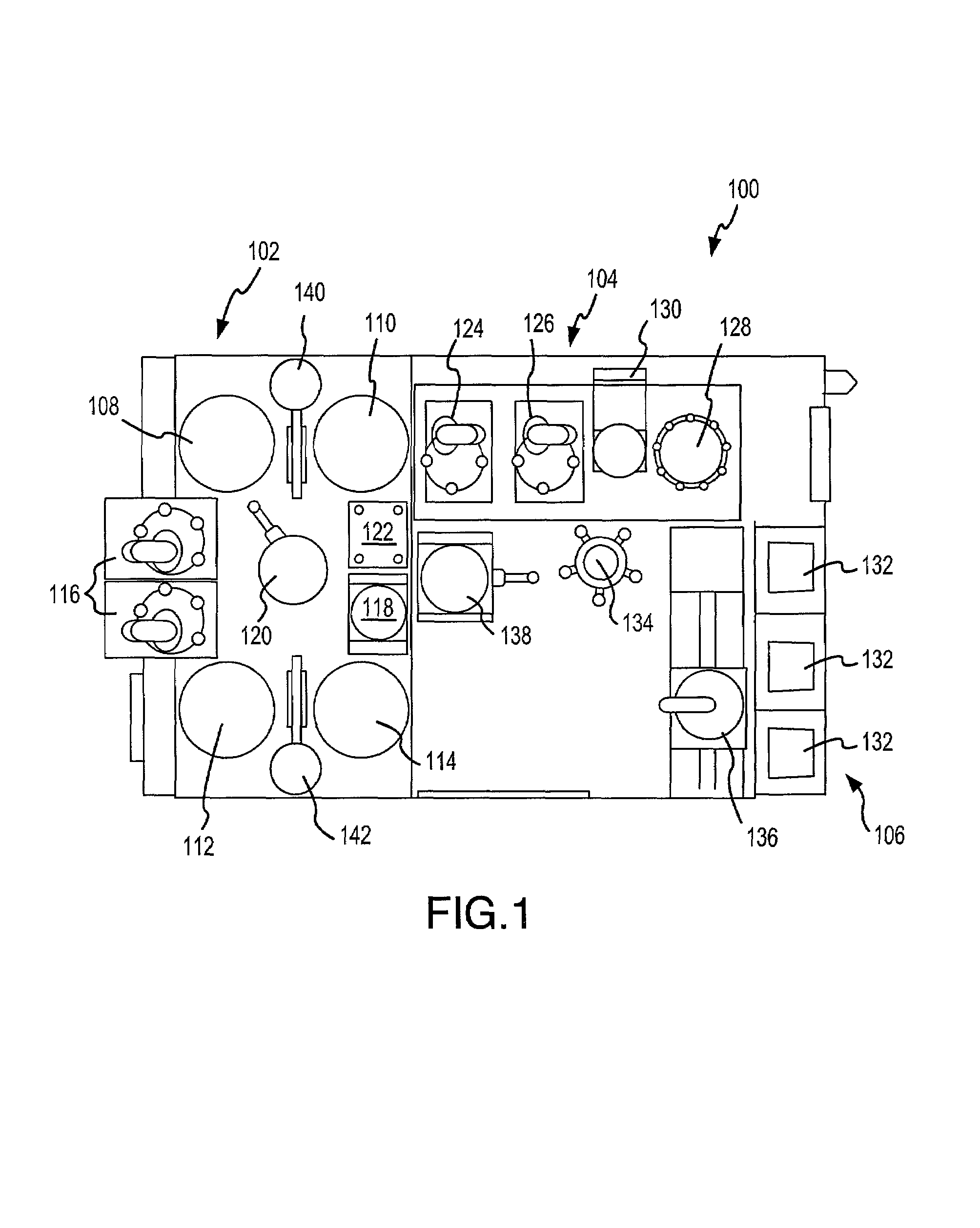
[0052]The following descriptions are of exemplary embodiments of the invention and the inventors' conception of the best mode, and are not intended to limit the scope, applicability or configuration of the invention in any way. Rather, the following description is intended to provide convenient illustrations for implementing various embodiments of the invention. As will become apparent, various changes may be made in the function and arrangement of the elements described in these embodiments without departing from the spirit and scope of the invention. Various exemplary implementations of the present invention may be applied to any polishing process utilizing chemically reactive slurry polishing agents. Certain representative implementations may include, for example, the polishing and / or planarization of: semiconductor wafers; integrated circuit wafers; magnetic data storage media, including computer hard drives and other magnetic mass storage media; optical data storage media inclu...


PUM

PropertyMeasurementUnit
lengthaaaaaaaaaa
depth of focusaaaaaaaaaa
radiusaaaaaaaaaa

Abstract

A method and apparatus for ‘through-the-pad’ delivery of slurry polishing agents directly to the land areas of a polishing pad is disclosed. The present invention further provides for improved control of the chemical composition of the slurry to address loss of chemical reactivity of the slurry during the polishing cycle. Additionally, various groove modifications to the polishing surface of the pad are also disclosed for improved slurry retention over substantially the entire surface of the polishing pad and reduction of the slow band effect. The present invention thus provides for a higher degree of planarization and uniformity of material removed from the surface of a processed workpiece in order to eliminate, or otherwise reduce, small-scale roughness and large-scale topographic differentials as well as to reduce the Cost-of-Ownership associated with slurry costs.

Description

FIELD OF INVENTION[0001]The present invention generally relates to a method and apparatus for polishing or planarizing workpieces such as, for example, semiconductor wafers, magnetic recording discs, and the like. More particularly, the present invention relates to a method and apparatus for controlling slurry distribution in a Chemical Mechanical Planarization process.BACKGROUND OF THE INVENTION[0002]Many electronic and computer-related products (i.e., semiconductors, computer hard disks, etc.) require highly polished surfaces in order to achieve optimum operational characteristics. Recent growth in the implementation of integrated circuit devices has generally resulted in a corresponding increase in demand for semiconductor wafers from which integrated circuit chips (“IC's”) are made. The need for higher density IC's, as well as the need for higher production throughput of IC's on a per-wafer basis, has resulted in a need for increasing the planarity of semiconductor wafer surface...

Claims


Application Information

Patent Timeline
Patent Type & Authority Patents(United States)
IPC IPC(8): B24B1/00B24B37/26B24B55/02
CPCB24B37/26B24B55/02B24B57/02H01L21/67219G11B5/8404C23F3/00H01L21/30625
Inventor LAURSEN, THOMASZHANG, GUANGYING
Owner SPEEDFAM IPEC
Learn More