Cyclone separator

a separator and cyclone technology, applied in the direction of separation process, filtration separation, vortex flow apparatus, etc., can solve the problems of large amount of machining waste contained in cutting liquid that cannot be reliably removed, clogging of filter membrane, affecting separation accuracy, etc., to achieve the effect of improving separation accuracy

Active Publication Date: 2008-01-01
INDUSTRIA CO LTD +1
View PDF6 Cites 40 Cited by
  • Summary
  • Abstract
  • Description
  • Claims
  • Application Information

AI Technical Summary

Benefits of technology

[0010]Accordingly, it is an object of the present invention for solving the problems above to provide a cyclone separator that is able to ensure a required flow rate using a small size-system, to improve the separation accuracy by separating particles into particles having an accurate particle diameter, and to permit the flow rate and particle diameter of the separated particles to be variable by a simple method.

Problems solved by technology

While the machining waste is removed, for example, with a filter membrane of the filter device, or the machining waste is removed by precipitation, there is a problem in that a large amount of the machining waste contained in the cutting liquid cannot be reliably removed within a short period of time using a small device.
The filter membrane may become clogged, and the clogged filter membrane needs to be cleaned after disassembling the filter device.
Since the filtration accuracy deteriorates and the filter membrane becomes readily clogged by repeated use, most of the filter membranes are in the form of disposable membranes.
Accordingly, the filter cost becomes expensive.
However, the pressure loss increases by narrowing the liquid flow-in passageway making it difficult to obtain an appropriate flow rate during processing.
In addition, forming the eddy flow from one liquid flow-in passageway generates a turbulence in the eddy flow, and a satisfactory separation accuracy cannot be obtained since particles cannot be easily separated into particles having accurate particle diameters.
While a high processing flow rate may be obtained by providing a plurality of liquid flow-in passageways for feeding the liquid, the cyclone separator necessarily becomes larger as a result of the plural pipe lines, making it difficult to provide an installation area.

Method used


Image

  • Cyclone separator
  • Cyclone separator
  • Cyclone separator

Examples


example

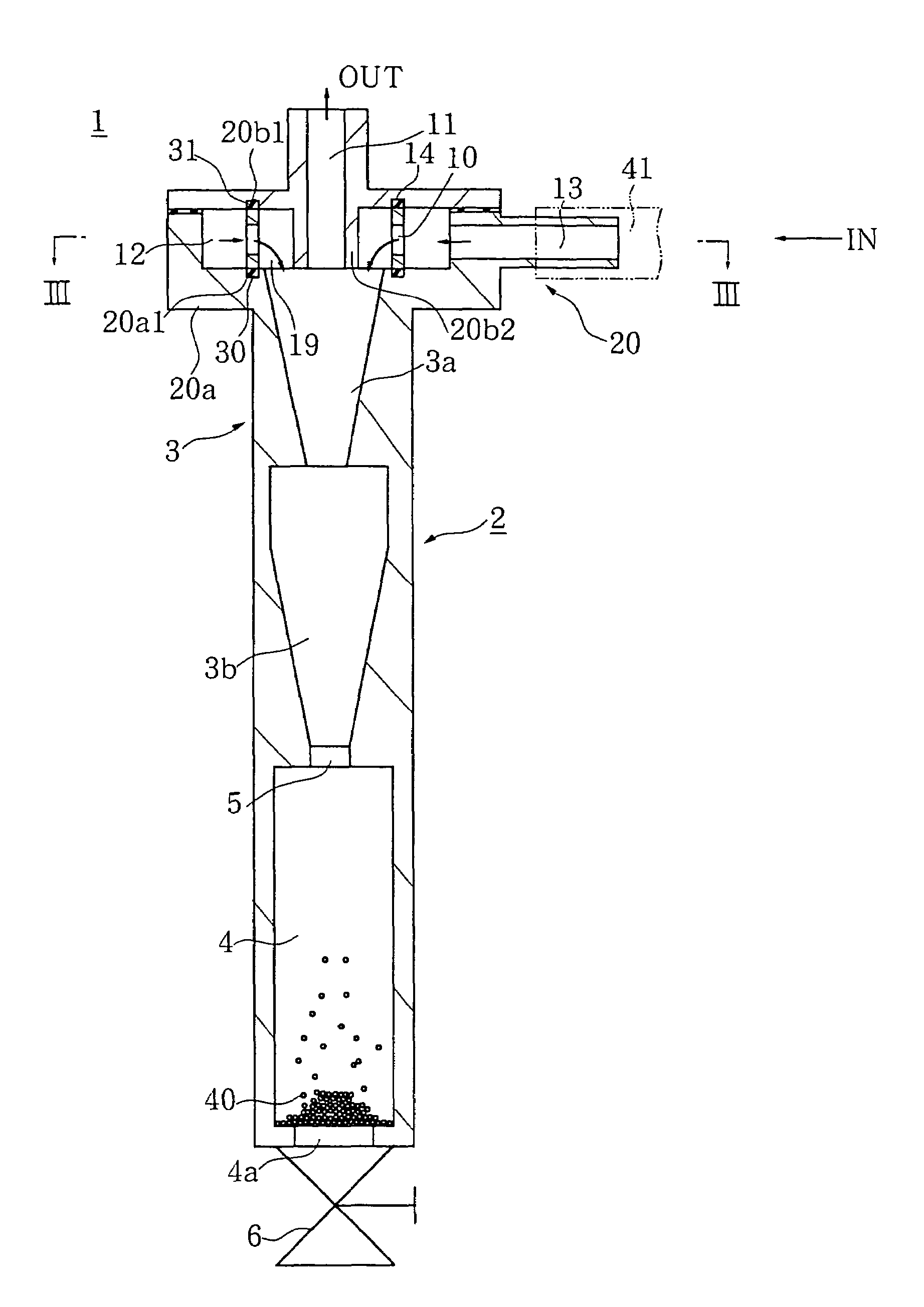
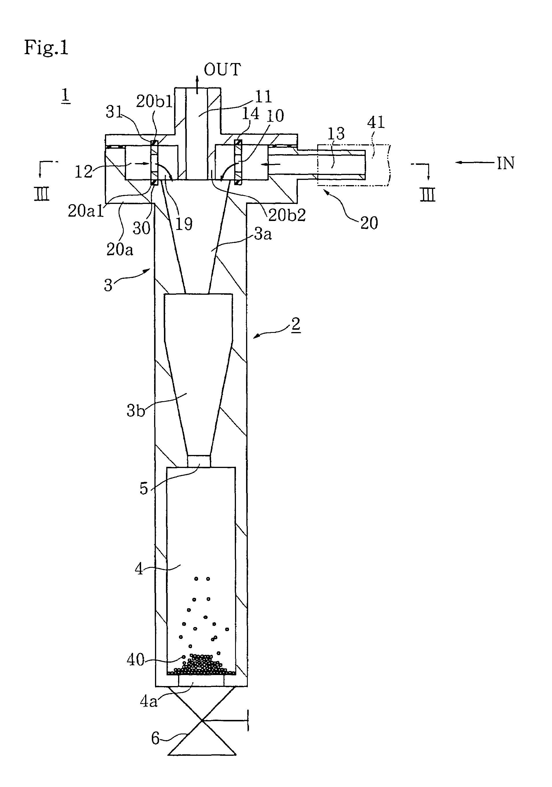
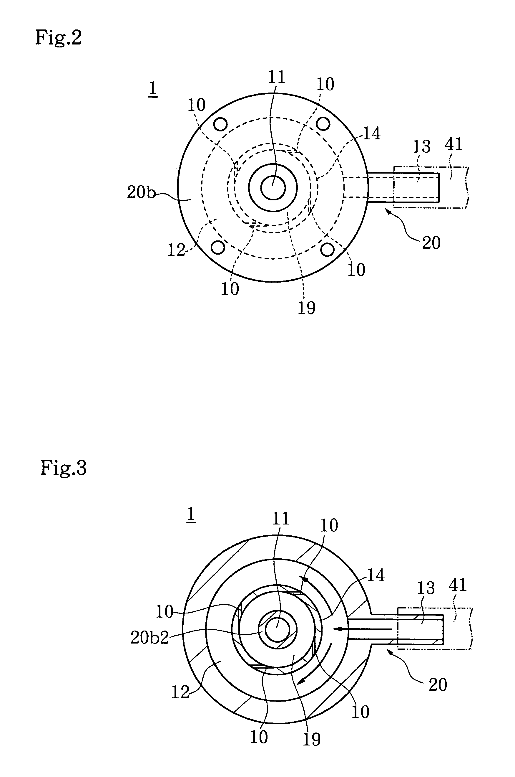
[0113]The separation treatment was performed using the cyclone separator in the example shown in FIGS. 24 and 25. A dispersion solution containing silica particles in ion-exchange water was used as the sample.

[0114]The cyclone separator used in this example comprises: a cyclone portion for generating an eddy flow at a given flow rate by feeding a liquid containing a fine substance from a liquid discharge passageway, transferring the fine substance to the outer side by applying a centrifugal force to discharge a fine substance-free liquid through the liquid flow-out passageway, and precipitating the separated fine substance by decelerating the eddy flow, orifice rings having two liquid discharge passageways, pressurizing chambers provided around the two liquid discharge passageways and communicating therewith, and a liquid introduction passageway for introducing the liquid containing the fine substance into the liquid pressurizing chamber. The liquid discharge passageway is formed by...


PUM

PropertyMeasurementUnit
distanceaaaaaaaaaa
particle diameteraaaaaaaaaa
lengthaaaaaaaaaa

Abstract

The present invention provides a cyclone separator made up of a cyclone portion for generating an eddy flow at a given flow rate by feeding a liquid containing a fine substance from liquid discharge passageways, for transferring the fine substance to an outer circumferential side by applying a centrifugal force to discharge the fine substance-free liquid from a liquid flow-out passageway, and for precipitating the fine substance by decelerating the eddy flow. The liquid discharge passageways are disposed at plural sites and the cyclone separator further contains a liquid pressurizing chamber formed around the plural liquid discharge passageways in communication therewith, and a liquid introduction passageway for introducing the liquid containing the fine substance into the liquid pressurizing chamber.

Description

BACKGROUND OF THE INVENTION[0001]1. Field of the Invention[0002]The present invention relates to a cyclone separator for removing a fine substance such as a fine powder produced as waste during a machining process.[0003]2. Description of the Related Art[0004]Machining processes are carried out by feeding a cutting liquid from a feed tank in a machining apparatus, and the used cutting liquid contains a fine powder as machining waste. The cutting liquid containing the fine powder as the machining waste is supplied to a filter device, and the cutting liquid devoid of the machining waste after filtering is recycled to the feed tank (for example, Japanese Unexamined Patent Application Publication No. 2001-137743).[0005]While the machining waste is removed, for example, with a filter membrane of the filter device, or the machining waste is removed by precipitation, there is a problem in that a large amount of the machining waste contained in the cutting liquid cannot be reliably removed w...

Claims


Application Information

Patent Timeline
Patent Type & Authority Patents(United States)
IPC IPC(8): B01D21/26B04C5/00B04C5/04B04C5/08B04C5/12B04C5/185B04C5/28C02F1/38
CPCB04C5/04B04C5/12B04C5/185B04C5/28
Inventor YOSHIDA, HIDETOFUKUI, KUNIHIROTAKAHASHI, KAZUAKINAKAMURA, JUNICHI
Owner INDUSTRIA CO LTD
Why Eureka
Try Eureka