
Shimming with MRI gradient

a magnetic resonance device and gradient technology, applied in measurement devices, instruments, acoustic wave reradiation, etc., can solve the problem of difficult to achieve uniform magnetic fields of less than 5 ppm over a large volume, and achieve the effect of accurate magnetic resonance measurement of the sampl

Inactive Publication Date: 2008-01-01
ASPECT IMAGING
View PDF8 Cites 11 Cited by
  • Summary
  • Abstract
  • Description
  • Claims
  • Application Information

AI Technical Summary

Problems solved by technology

Uniformity of magnetic fields to less than 5 ppm is very difficult to achieve over a large volume.

Method used


Image

  • Shimming with MRI gradient
  • Shimming with MRI gradient
  • Shimming with MRI gradient

Examples


Embodiment Construction

[0023]The following description is provided, alongside all chapters of the present invention, so as to enable any person skilled in the art to make use of said invention and sets forth the best modes contemplated by the inventor of carrying out this invention. Various modifications, however, will remain apparent to those skilled in the art, since the generic principles of the present invention have been defined specifically to a method of calibrating the shim coils of a magnetic resonance and to a device providing the same.

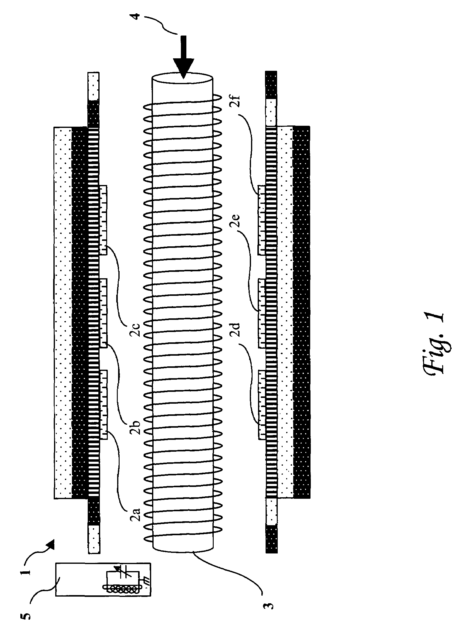
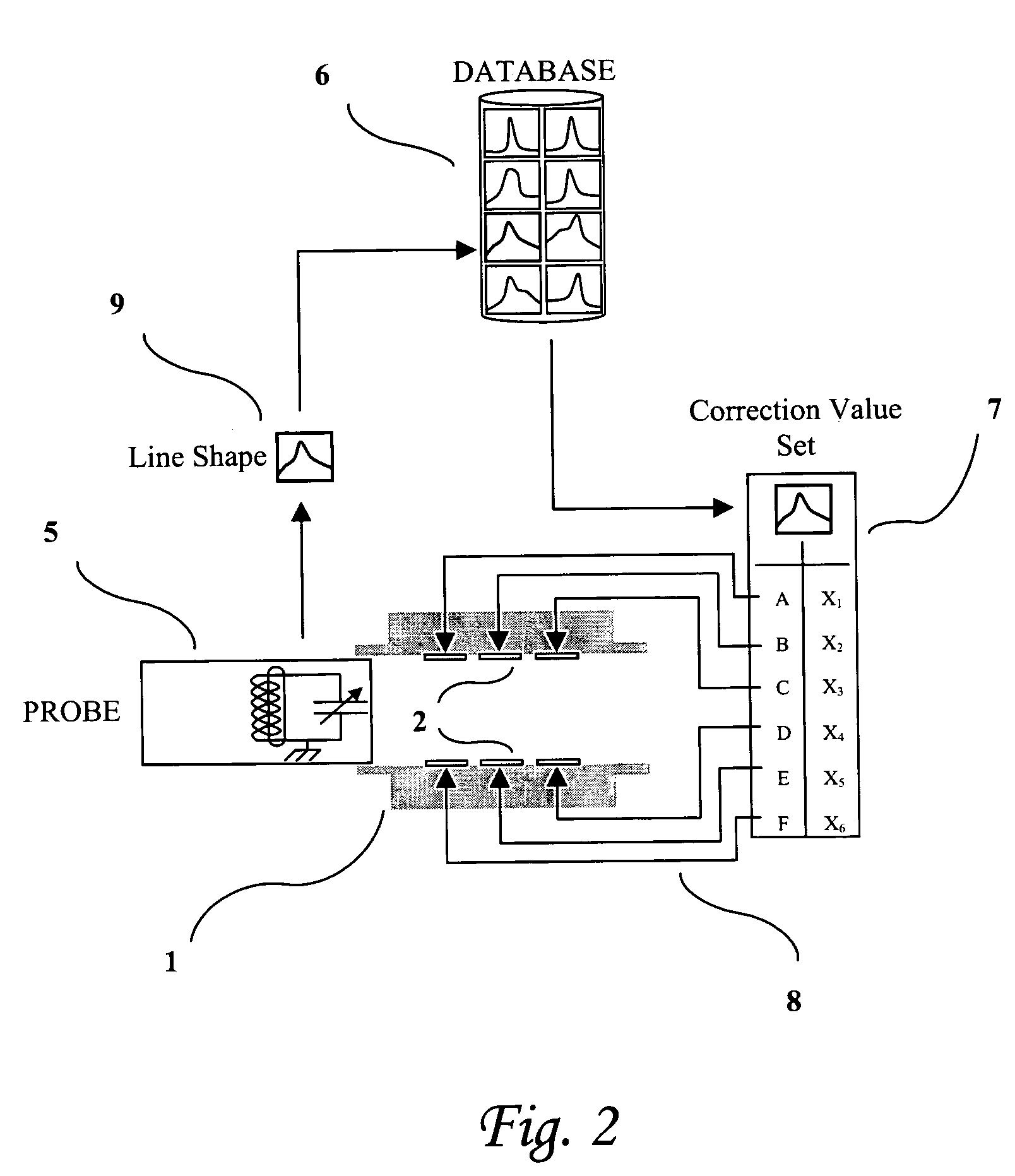
[0024]The term ‘correction value’ applies hereinafter to any parameter that effects the magnetic field around a shimming element such that the magnetic field around a sample is restored to uniformity following a disruption. Such a parameter could be the current through the coil, voltage across the coil, shape of the coil, or any other parameter.

[0025]The term ‘correction-current’ applies hereinafter to the size of the current applied to a shim coil such that the m...


PUM


Abstract

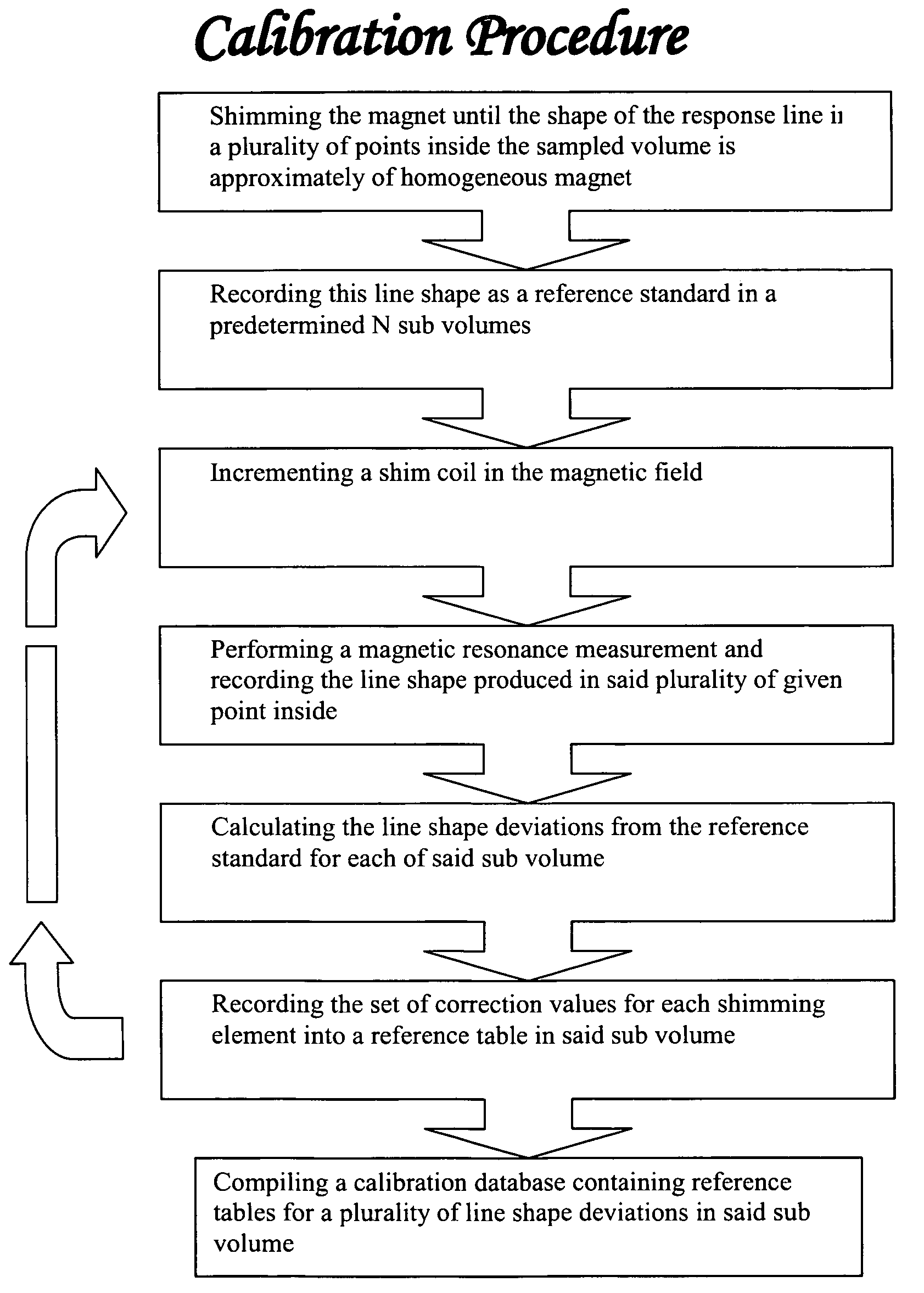
A method of correcting active shimming element of a magnetic resonance device, including providing a set of correction values for each shimming element for a given N sub volumes, wherein N is an integer number greater than or equal to 1, detecting irregularities in the magnetic field of the sample regions, optimizing all the shimming elements according to the set of correction values, assessing the regularity of the corrected magnetic field, and reiterating the process until field uniformity is achieved, such that an accurate magnetic resonance measurement of the sample is achieved after a minimum number of iterations.

Description

FIELD OF INVENTION[0001]The present invention generally relates to a method of calibrating the shim coils of a magnetic resonance device.BACKGROUND OF THE INVENTION[0002]A magnetic resonance imaging device produces a measurement of a sample which is based upon its molecular structure. The sample is subjected to a polarizing magnetic field which has the effect of aligning the spins of all the atomic nuclei of the sample. Radio waves at a frequency close to the Lamor frequency of the nuclei are then used to excite the nuclei such that their magnetic alignment is reversed. Once the excitation is removed the nuclei return to their original state by emitting characteristic radio signals. It is these radio signals that can be used to image the sample.[0003]The exact Lamor frequency is dependent upon the precise magnetic field. By creating a magnetic field gradient within the sample cavity the source of these signals can be located such that an overall image of the sample can be constructe...

Claims


Application Information

Patent Timeline
Patent Type & Authority Patents(United States)
IPC IPC(8): G01V3/00
CPCG01R33/3875G01R33/543
Inventor RAPOPORT, URIKATZNELSON, EHUD
Owner ASPECT IMAGING
Learn More