Hydrocarbon polluted shallow groundwater magnetic resonance detection device and hydrocarbon polluted shallow groundwater magnetic resonance detection method
A technology of polluted water and magnetic resonance, applied in the direction of detection by electronic magnetic resonance/NMR/NMR, analysis by nuclear magnetic resonance, etc. The effect of uneven magnetic field and improved signal-to-noise ratio
- Summary
- Abstract
- Description
- Claims
- Application Information
AI Technical Summary
Problems solved by technology
Method used
Image
Examples
Embodiment 1
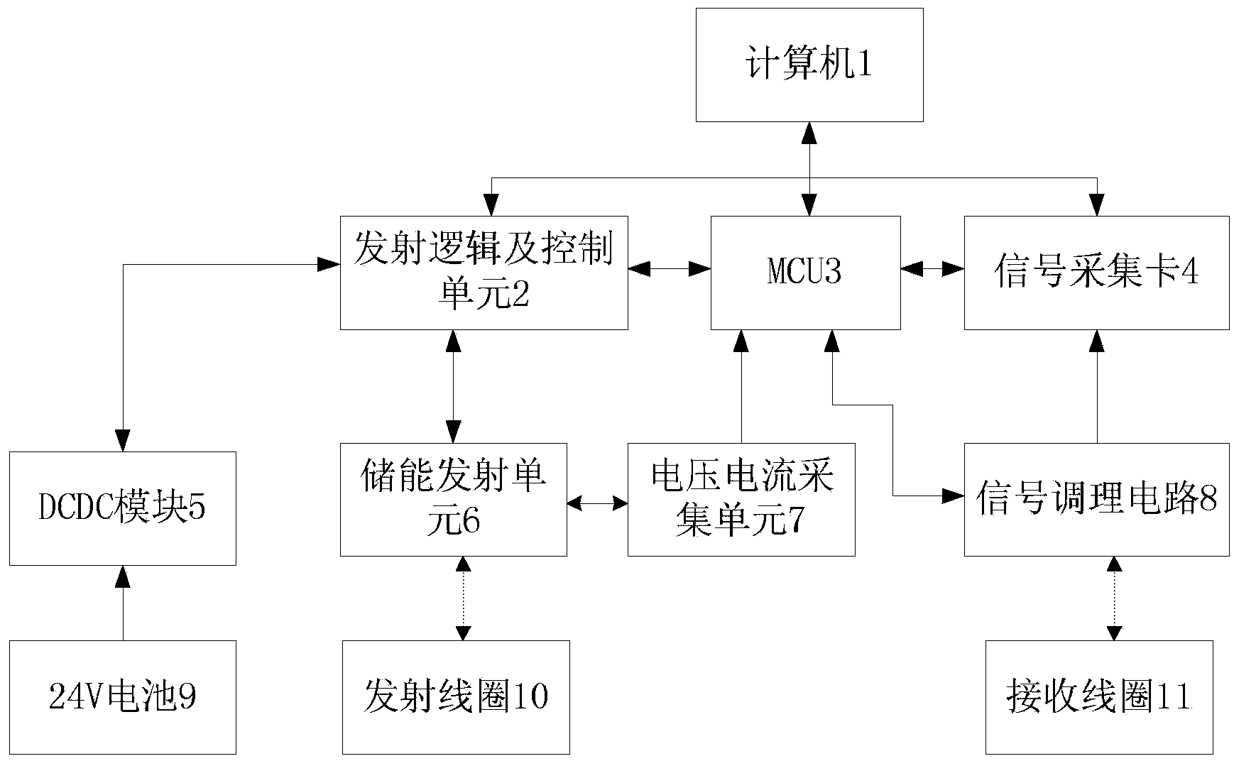
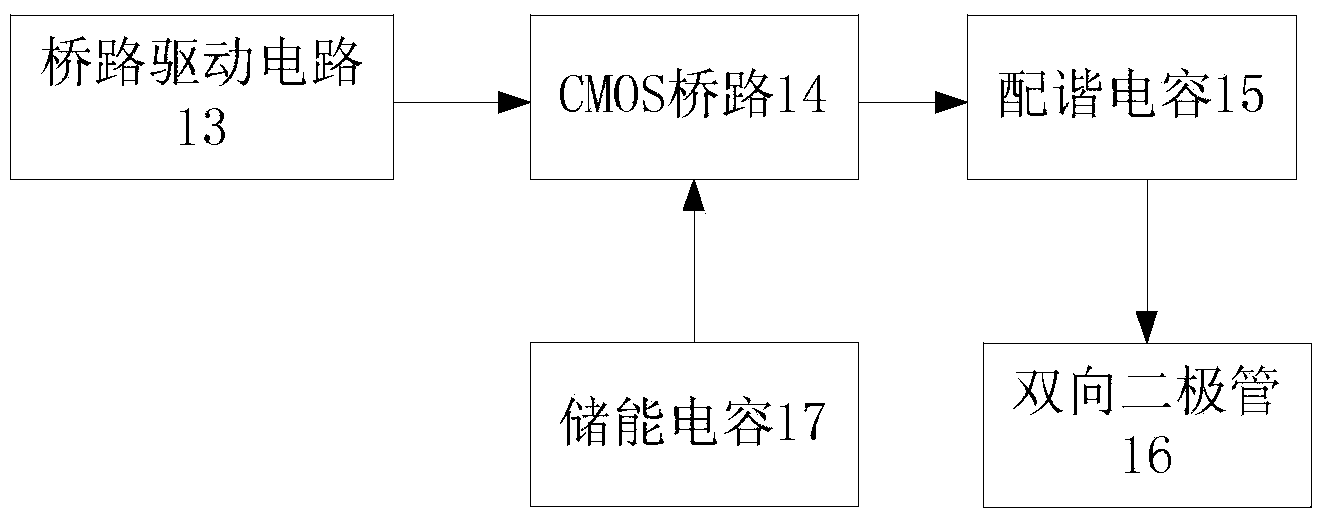
[0040] Computer 1 is connected to MCU3 through a USB to 485 cable, computer 1 is connected to signal acquisition card 4 through a network cable, MCU3 is connected to signal acquisition card 4 through a synchronous signal line, signal acquisition card 4 is connected to signal conditioning circuit 8 through a signal transmission line, and the signal conditioning The circuit 8 is connected to the receiving coil 11, the signal conditioning circuit 8 is connected to the MCU3 for configuration, the computer 1 is connected to the transmitting logic and control unit 2, the MCU3 is connected to the transmitting logic and control unit 2, and the transmitting logic and control unit 2 is connected to the DCDC module 5 , the transmitting logic and control unit 2 is connected to the energy storage transmitting unit 6, the energy storage transmitting unit 6 is connected to the voltage and current acquisition unit 7, the voltage and current acquisition unit 7 is connected to the MCU3, the energ...
Embodiment 2
[0053] The magnetic resonance detection method of hydrocarbon-polluted shallow groundwater works according to the following steps:
[0054] a. The permanent magnet 12 is placed in the area to be tested, and the magnetic field strength of the area to be tested is increased by about 10 times. According to the principle of nuclear magnetic resonance, the corresponding transmission frequency is also increased by about 10 times, and the frequency of the received signal is also increased by about 10 times. Spread the transmitting coil 10 and the receiving coil 11 respectively in the uniform range of the magnetic field within the range of the permanent magnet 12, the transmitting coil 10 and the receiving coil 11 are all laid into a 5-meter-long square and the receiving coil 11 is laid on the inner side of the transmitting coil 10 and basically overlaps place.
[0055] b. Connect the transmitting coil 10 to both ends of the bridge, connect the receiving coil 11 to the two ends of the...
PUM
 Abstract
Description
Claims
Application Information
 - R&D
- Intellectual Property
- Life Sciences
- Materials
- Tech Scout
- Unparalleled Data Quality
- Higher Quality Content
- 60% Fewer Hallucinations
Browse by: Latest US Patents, China's latest patents, Technical Efficacy Thesaurus, Application Domain, Technology Topic, Popular Technical Reports.
© 2025 PatSnap. All rights reserved.Legal|Privacy policy|Modern Slavery Act Transparency Statement|Sitemap|About US| Contact US: help@patsnap.com


