Method and magnetic resonance system for determining the flip angle distribution in a volume of an examination subject

a magnetic resonance system and volume technology, applied in the field of method and magnetic resonance system for determining the flip angle distribution in the volume of an examination subject, can solve the problems of subject-specific optimization, inability to see pathological structures, and inability to adulterate the measuremen

Inactive Publication Date: 2007-04-19
SIEMENS HEALTHCARE GMBH
View PDF10 Cites 18 Cited by
  • Summary
  • Abstract
  • Description
  • Claims
  • Application Information

AI Technical Summary

Benefits of technology

[0010] An object of the present invention is to allow the radio-frequency field distributions that occur with a wide variety of transmission configurations in magnetic resonance tomography to be quickly determined so that the optimal, individual parameters for subsequent MR measurements can be determined on the basis of these values.

Problems solved by technology

Spatial fluctuations in the field strength of the excited B1 field therefore lead to unwanted variations in the acquired magnetic resonance signal that can adulterate the measurement result.
Contrast and brightness of the acquired magnetic resonance images therewith vary in the mapped tissue and can lead, in the worst case, to the situation in which pathological structures are not visible.
A subject-specific optimization (i.e. an optimization that is directly adapted to the current examination subject to be understood), however, is therewith not possible.
This does in fact allow an object-dependent adjustment, but these measurements are extraordinarily time-consuming.
This method is thus not practical in practice as an adjustment method.

Method used


Image

  • Method and magnetic resonance system for determining the flip angle distribution in a volume of an examination subject
  • Method and magnetic resonance system for determining the flip angle distribution in a volume of an examination subject
  • Method and magnetic resonance system for determining the flip angle distribution in a volume of an examination subject

Examples


Embodiment Construction

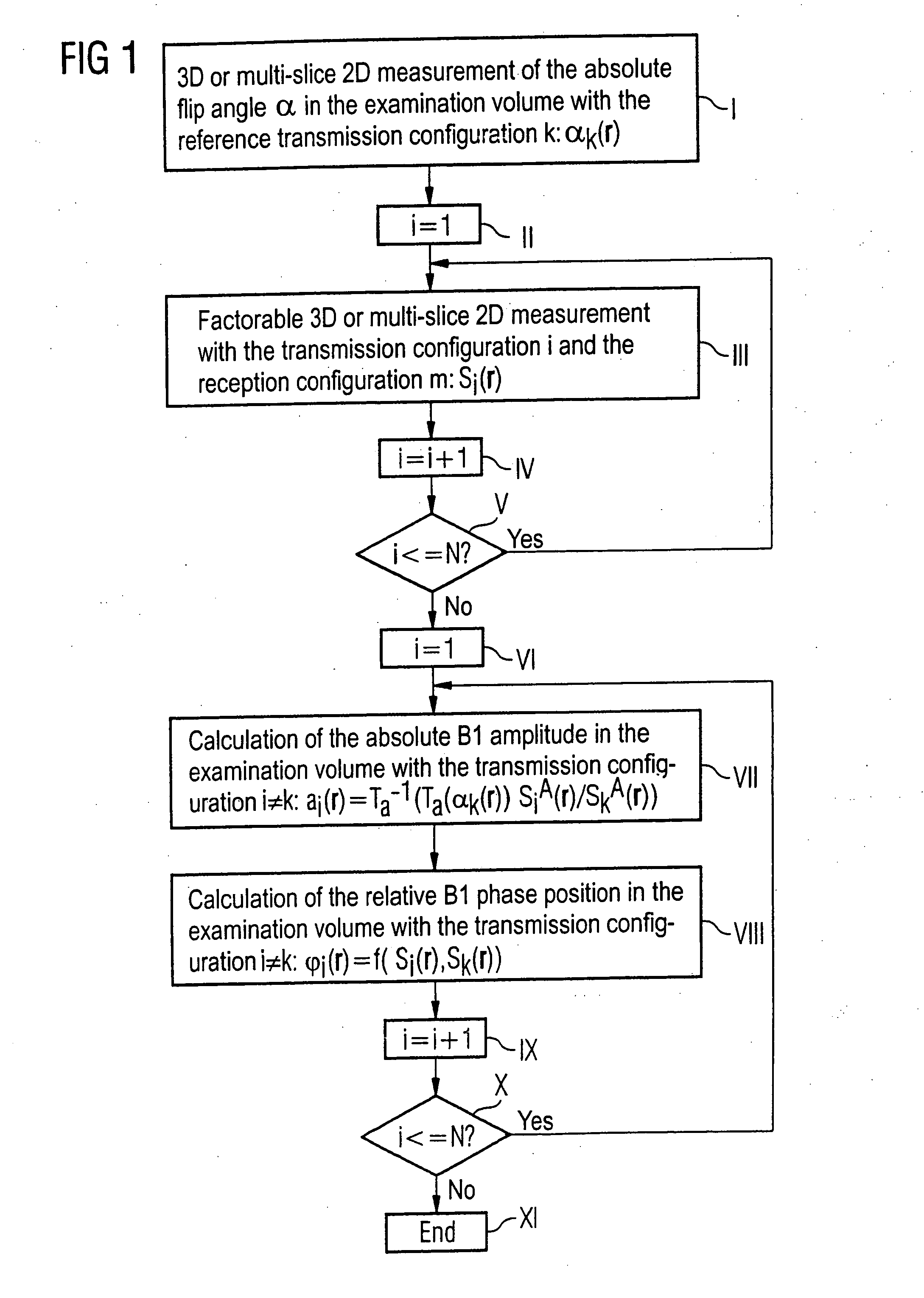
[0051] A possible measurement and calculation process according to an embodiment of the inventive method is shown in FIG. 1 using a workflow plan.

[0052] In step I the absolute flip angle distribution αk(r) in the examination volume is thereby initially measured with the reference transmission configuration k with a three-dimensional or multi-slice two-dimensional method. This can ensue, for example, with the method described in United States Patent Application Publication 2005 / 0073304 A1 or 2004 / 0164737 A1. Subsequently, a control variable i is initially set to 1 in step II. In a subsequent loop the factorizable three-dimensional or multi-slice two-dimensional measurements are then respectively implemented with all transmission configurations i=1 through N (as already described above). The result are [sic] magnetic resonance images, wherein the spatial image signal distribution can be designated as Si(r). The same reception configuration should thereby respectively be selected.

[00...


PUM


Abstract

In a method for determination of flip angle distributions for various antenna transmission configurations in a magnetic resonance system, magnetic resonance measurements are implemented with the various transmission configurations, with the reception configuration being identical for all implemented magnetic resonance measurements, and all magnetic resonance measurements for the various transmission configurations are implemented with a specific pulse sequence. This pulse sequence is selected such that the total function that describes the dependency of the image signal at a specific location on the flip angle achieved at this location with the radiated radio-frequency field, as well as on further MR-relevant parameters, can be factored into a first sub-function that describes the dependency of the image signal on the achieved flip angle and a second sub-function (Tb) that describes the dependency of the image signal on the further MR-relevant parameters, and such that the functional dependency of the image signal on the achieved flip angle is known. The absolute flip angle distribution is measured for a reference transmission configuration, and the flip angle distributions of the other transmission configurations are then respectively determined on the basis of the absolute flip angle distribution of the reference transmission configuration and on the basis of the ratio of the spatially-dependent image signals of the magnetic resonance measurements of the respective transmission configuration to the corresponding spatially-dependent image signals of the magnetic resonance measurement of the reference transmission configuration.

Description

BACKGROUND OF THE INVENTION [0001] 1. Field of the Invention [0002] The present invention concerns a method for determining flip angle distributions for various antenna transmission configurations in at least one specific volume region within an examination subject in a magnetic resonance system, wherein the magnetic resonance system has a radio-frequency antenna with a number of resonator elements that (in different transmission configurations) can be excited individually or in groups for generation of linearly-independent radio-frequency field distributions in an examination volume enclosing the examination subject. The invention also concerns a magnetic resonance system suitable for implementation of such a method, with a corresponding radio-frequency antenna and a computer program product that can be loaded into a memory of a programmable control device of such a magnetic resonance system for implementation of the method. [0003] 2. Description of the Prior Art [0004] Magnetic re...

Claims


Application Information

Patent Timeline
Patent Type & Authority Applications(United States)
IPC IPC(8): G01V3/00
CPCG01R33/246G01R33/3415G01R33/5612G01R33/5659G01R33/583
Inventor FEIWEIER, THORSTEN
Owner SIEMENS HEALTHCARE GMBH
Why Eureka
Try Eureka