
Method for controlling an RF transmission device, and MR apparatus and RF device for implementing the method

a transmission device and transmission device technology, applied in the direction of measuring devices, magnetic measurements, instruments, etc., can solve the problems of limited function of the rf device, and achieve the effect of preventing the radiated rf power

Active Publication Date: 2006-09-07
SIEMENS HEALTHCARE GMBH
View PDF8 Cites 19 Cited by
  • Summary
  • Abstract
  • Description
  • Claims
  • Application Information

AI Technical Summary

Benefits of technology

[0014] An object of the present invention is to provide a method for controlling an RF device that reliably prevents the radiated RF power from exceeding a limit value that is not dangerous to the patient, even for a subject of examination that is moving relative to the transmit field, while at the same time permitting this safe limit value to be approached as closely as possible, so that the measurement (data acquisition) can take place within the limit value with as high an RF transmission power as possible. A further object is to provide a corresponding magnetic resonance tomography system, as well as an RF control device, with which such a method can be implemented.
[0037] Also within the scope of the present invention is a corresponding RF control device having a measurement value input for the measurement values, a position value input for the position values, and a control signal output for control signals. The RF control device is configured such that at chronological intervals measurement values are measured and position values are determined, and on the basis of the measurement values and position values corresponding exposure values are determined that represent a physiological effectiveness that the RF pulses have on a subject exposed to the RF pulses. In addition, the RF control device ensures that, based on the sum of a multiplicity of exposure values, exposure control values are formed, and that a control signal that effects the limitation of the functioning of the RF device is outputted at the control signal output if an exposure control value reaches or exceeds an exposure limit value.

Problems solved by technology

The RF device is limited in its functioning if an exposure control value reaches or exceeds an exposure limit value.

Method used


Image

  • Method for controlling an RF transmission device, and MR apparatus and RF device for implementing the method
  • Method for controlling an RF transmission device, and MR apparatus and RF device for implementing the method
  • Method for controlling an RF transmission device, and MR apparatus and RF device for implementing the method

Examples


Embodiment Construction

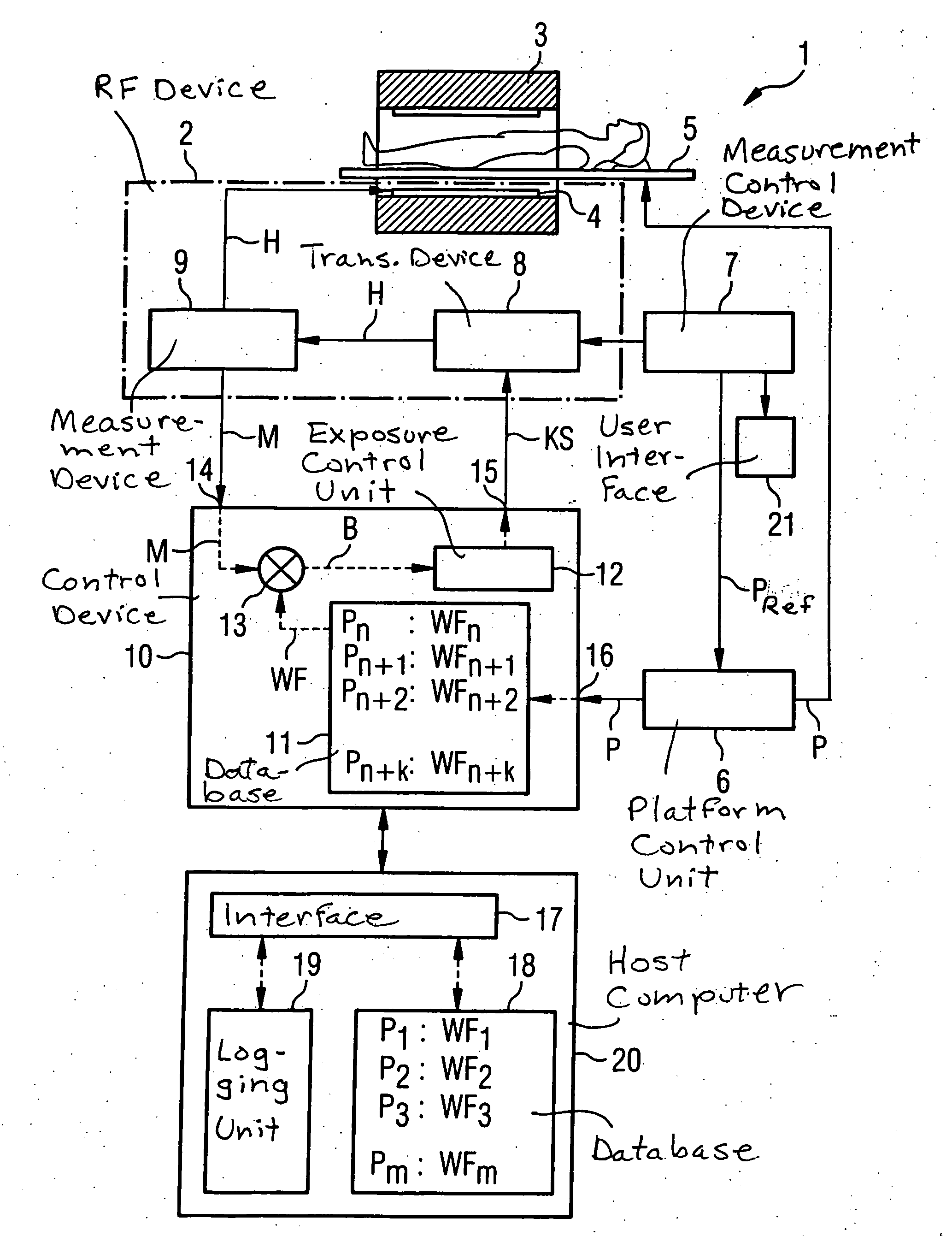
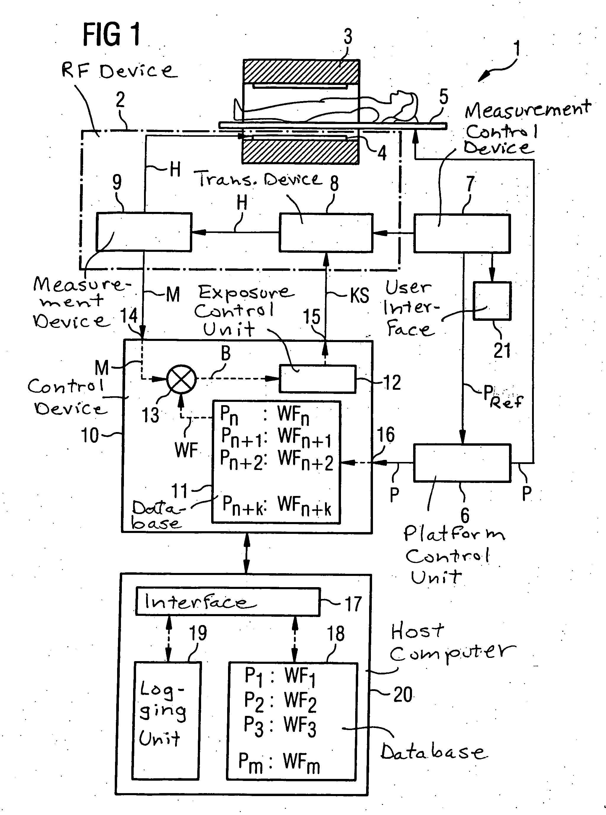
[0042]FIG. 1 schematically shows the basic components of a magnetic resonance tomography system 1 for explaining the present invention. These include the MR scanner, having a basic field magnet 3, as well as an RF transmission / reception antenna 4. In the following, this RF antenna 4 is referred to for short as a transmission coil 4, because the present invention relates to the monitoring of the radiated RF power. Such a transmission coil 4, which surrounds the entire measurement space of the scanner, is standard also designated a whole-body coil or body coil. It can be constructed, for example, in the manner of an antenna type known as a birdcage antenna. Within the measurement space surrounded by the transmission coil 4, in which the transmission field essentially extends, there is situated an examination platform 5 on which an examination subject O, i.e., the patient, can be positioned. Via a drive system (not shown), platform 5 can be moved through the tomograph along the longitu...


PUM


Abstract

In a method for controlling a radio-frequency device, and a magnetic resonance tomography system and a radio-frequency control device wherein the method is implemented, the RF device of a magnetic resonance tomography system is emitted during a magnetic resonance measurement of an examination subject that is moving relative to the transmission field of the RF device. The RF device emits RF pulses at chronological intervals, and measurement values are measured at chronological intervals. At chronological intervals, position values are determined that represent a current position of the examination subject relative to the transmission field. On the basis of the measurement values and the position values, exposure values are determined that represent a physiological degree of effectiveness that the RF pulses have on the subject exposed to the RF pulses. Based on a multiplicity of exposure values, exposure control values are respectively formed. The RF device is limited in its functioning if an exposure control value reaches or exceeds an exposure limit value.

Description

BACKGROUND OF THE INVENTION [0001] 1. Field of the Invention [0002] The present invention relates to a method for controlling a radio-frequency device for a magnetic resonance tomography system, as well as to a magnetic resonance tomography system having such a radio-frequency device, and to a corresponding radio-frequency (RF) control device for executing such a method. [0003] 2. Description of the Prior Art [0004] In the field of medicine, in recent years an imaging based on modality, detection and measurement of the nuclear spins of protons in a region of the body. The imaging is essentially carried out in three steps. First, a strong, stable, homogenous magnetic field is generated around the body region, producing a stable (aligned) orientation of the protons in the relevant bodily region. This stable orientation is then altered by supplying electromagnetic RF energy. Thirdly, this energy stimulation is terminated, and the nuclear resonance signals that have arisen in the body a...

Claims


Application Information

Patent Timeline
Patent Type & Authority Applications(United States)
IPC IPC(8): G01V3/00
CPCG01R33/28G01R33/56375G01R33/56383
Inventor BIELMEIER, WOLFGANGLUDWIG, KLAUSSCHNETTER, VOLKER
Owner SIEMENS HEALTHCARE GMBH
Learn More