Method and apparatus for controlling t1 recovery process in magnetic resonance measurements

a magnetic resonance and recovery process technology, applied in the field of nuclear magnetic resonance imaging methods and systems, can solve the problems of reducing image sensitivity and excessive dead time, and achieve the effects of quick restoration of longitudinal magnetization, enhanced rd effect, and increased rd

Inactive Publication Date: 2010-04-15
WALD LAWRENCE L +2
View PDF6 Cites 19 Cited by
  • Summary
  • Abstract
  • Description
  • Claims
  • Application Information

AI Technical Summary

Benefits of technology

[0008]The present invention is a method and apparatus for controlling the duration of the magnetization recovery period in a magnetic resonance measurement cycle by employing the radiation damping (RD) phenomenon. More specifically, the received MR signal is coupled to a feedback circuit which imposes a phase shift and amplifies the resulting RD feedback signal. This RD feedback signal is applied to an RF coil disposed near the subject of the MR examination and its field quickly restores longitudinal magnetization in the subject. Referring particularly to FIG. 4, this radiation damping indicated by reference number 3 is applied after the MR signal readout 2 and it enables the next measurement cycle to be performed in a much shorter TR without loss of signal or image SNR.
[0009]This invention recognizes that the feedback circuit can be used to enhance the RD effect and that the increased RD effect can be employed to enable controlled and vastly accelerated recovery of the longitudinal magnetization. In preliminary experiments, we have found that we can achieve 100% of the recovery of the longitudinal magnetization by activating the feedback device for only 10 ms. On the other hand, natural T1 recovery in this sample (e.g., brain tissue) takes more than 3000 ms to achieve a 95% recovery by natural T1 relaxation. The feedback enhanced RD effect can thus be employed to substantially reduce the TR of existing pulse sequences.
[0010]An object of the present invention is to shorten total scan time by shortening the TR of pulse sequences used to acquire data. Using the feedback enhanced RD effect, a scan performed with the RARE imaging sequence (also known as Fast Spin Echo (FSE) or Turbo Spin Echo (TSE) may be shortened. In this scan a long TR is typically used to allow full recovery of the longitudinal magnetization by natural T1 processes. For sequences with a limited number of slices, this leads to excessive dead time. For example, the excitation and encoding period of a typical 12-echo sequence is about 150 ms. If a 256 image matrix is desired, this requires 256 / 12=22 excitations to acquire the imaging matrix. At a TR=3 s per excitation this requires over a minute of scan time. If the same longitudinal recovery is achieved in 10 ms of enhanced RD feedback, then the TR can be set to 160 ms, providing an imaging time of less than 2 s. Since the efficiency of the recovery is improved the image sensitivity would be identical, but with a vast saving in imaging time, and improved efficacy for movement in difficult patient populations.
[0011]Another object of the present invention is to increase the sensitivity of existing pulse sequences and thereby increase the SNR of the image reconstructed from the data they acquire. For example, in a typical spoiled gradient-recalled echo pulse sequence such as FLASH, a short TR is used to obtain acceptable imaging times, but the long (approximately 1 s) T1 recovery of tissue requires a low flip angle RF excitation pulse be used to ensure longitudinal magnetization is preserved for the duration of the scan. This greatly reduces the sensitivity of the image. For a proton density-weighted FLASH image, typically a TR of 50 ms and flip angle of 10° is used to preserve the high level of steady state magnetization needed to maintain proton density contrast. By providing full T1 recovery using the present invention within the 50 ms TR, a 90 degree RF excitation may be used, which improves the sensitivity and SNR by a factor of 7.

Problems solved by technology

For sequences with a limited number of slices, this leads to excessive dead time.
This greatly reduces the sensitivity of the image.

Method used


Image

  • Method and apparatus for controlling t1 recovery process in magnetic resonance measurements
  • Method and apparatus for controlling t1 recovery process in magnetic resonance measurements
  • Method and apparatus for controlling t1 recovery process in magnetic resonance measurements

Examples


Embodiment Construction

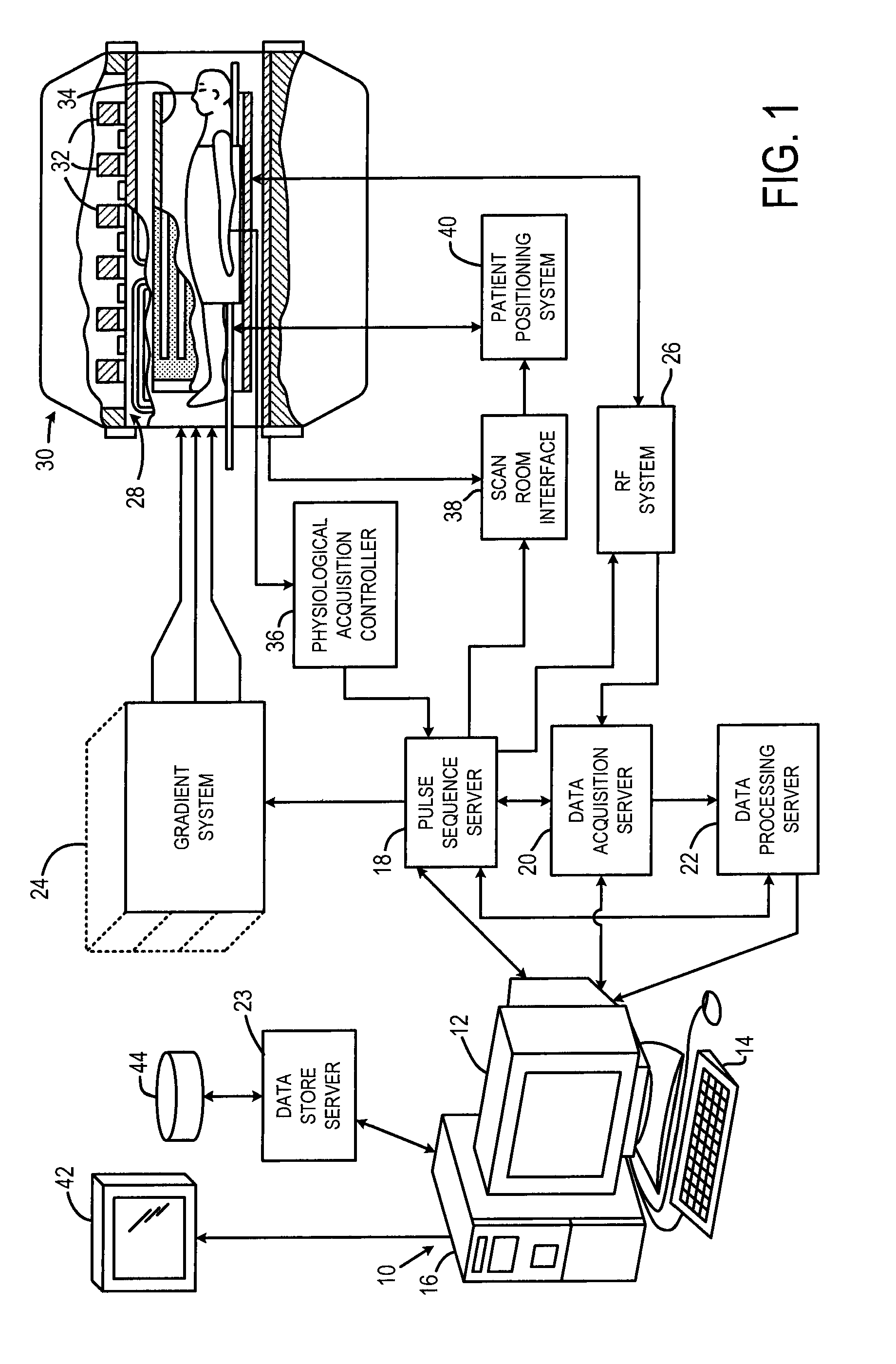
[0019]Referring particularly to FIG. 1, the preferred embodiment of the invention is employed in an MRI system. The MRI system includes a workstation 10 having a display 12 and a keyboard 14. The workstation 10 includes a processor 16 which is a commercially available programmable machine running a commercially available operating system. The workstation 10 provides the operator interface which enables scan prescriptions to be entered into the MRI system.

[0020]The workstation 10 is coupled to four servers: a pulse sequence server 18; a data acquisition server 20; a data processing server 22, and a data store server 23. In the preferred embodiment the data store server 23 is performed by the workstation processor 16 and associated disc drive interface circuitry. The server 18 is performed by a separate processor and the servers 20 and 22 are combined in a single processor. The workstation 10 and each processor for the servers 18, 20 and 22 are connected to an Ethernet communications ...


PUM


Abstract

Radiation damping (RD) is employed to hasten the recovery of longitudinal magnetization after RF excitation and signal readout in a magnetic resonance measurement cycle. A switch driven by the pulse sequence that performs the measurement cycle energizes a feedback RF coil driven by an amplified and phase shifted portion of the received MR signal. The recovery of longitudinal magnetization is thus under direct control of the MR system and enables the reduction of the otherwise inefficient waiting times that are required for natural T1 recovery of the excited spin magnetization. This enables shortened acquisition times, improved sensitivity, better spatial and temporal resolution, and reduction of motion artifacts that result from long acquisition times.

Description

BACKGROUND OF THE INVENTION[0001]The field of the invention is nuclear magnetic resonance imaging methods and systems. More particularly, the invention relates to the controlled recovery of longitudinal magnetization after the readout of MR signals from a pulse sequence.[0002]When a substance such as human tissue is subjected to a uniform magnetic field (polarizing field B0), the individual magnetic moments of the spins in the tissue attempt to align with this polarizing field, but precess about it in random order at their characteristic Larmor frequency. If the substance, or tissue, is subjected to a magnetic field (excitation field B1) which is in the x-y plane and which is near the Larmor frequency, the net aligned moment, or longitudinal magnetization, may be rotated, or “tipped”, into the x-y plane to produce a net transverse magnetic moment, or transverse magnetization. An MR signal is emitted by the excited spins after the excitation signal B1 is terminated and this MR signal...

Claims


Application Information

Patent Timeline
Patent Type & Authority Applications(United States)
IPC IPC(8): G01R33/36G01R33/54
CPCG01R33/561
Inventor WALD, LAWRENCE L.HUANG, SUSIE Y.WITZEL, THOMAS
Owner WALD LAWRENCE L
Why Eureka
Try Eureka