Eureka AIR delivers breakthrough ideas for toughest innovation challenges, trusted by R&D personnel around the world.

Electroosmotic micropump with planar features

a micropump and electroosmotic technology, applied in the field of non-mechanical micropumpes, can solve the problems of high flow rate, high pressure and flow rate of electroosmotic flit pumps, limited use of non-mechanical micropumpes in medical and biological applications, etc., to achieve favorable geometries and improve micropump performance.

Inactive Publication Date: 2008-01-08
THE BOARD OF TRUSTEES OF THE LELAND STANFORD JUNIOR UNIV
View PDF41 Cites 30 Cited by
  • Summary
  • Abstract
  • Description
  • Claims
  • Application Information

AI Technical Summary

Benefits of technology

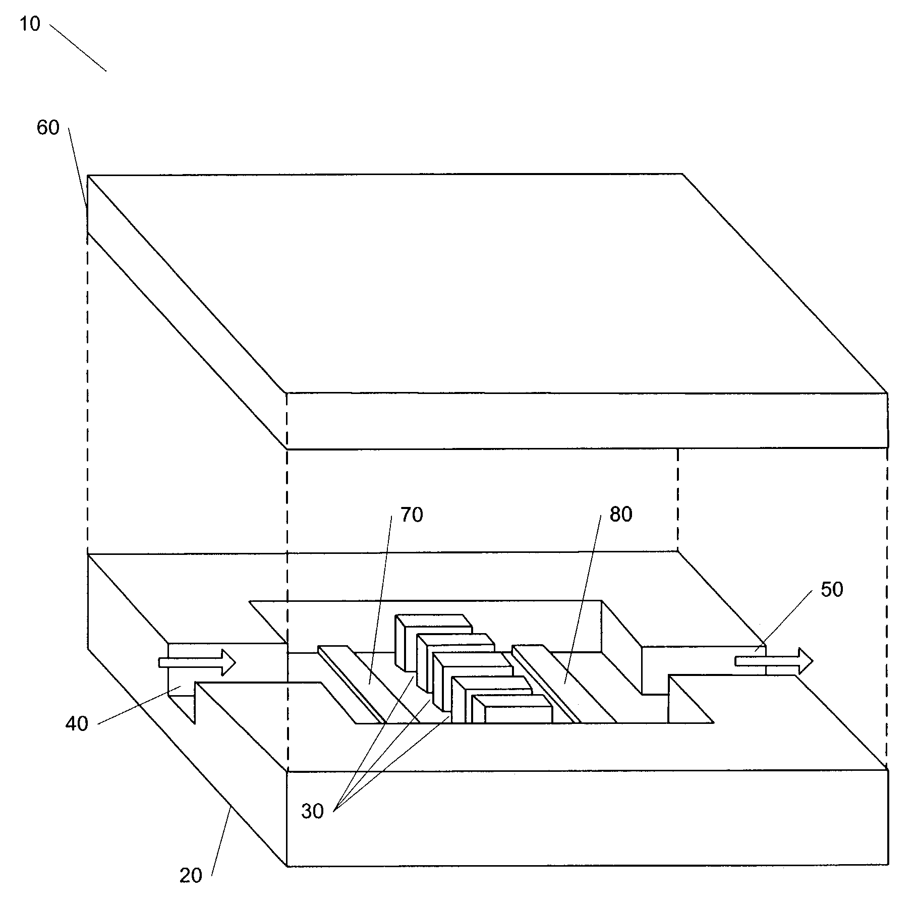
[0009]The features of the present invention in one aspect include a multiple-slot electroosmotic flow (EOF) pumping region; the use of deep reactive ion-enhanced etching to produce EOF pumping regions with favorable geometries; treatment of a silicon substrate to provide suitable electrical insulation; and additional treatment of the silicon substrate to improve micropump performance.

Problems solved by technology

As a result, these types of non-mechanical micropumps have limited use in medical and biological applications.
A disadvantage of EO pumps is the complexity of integrating porous media, e.g., packed silica particle beds, into microdevices.
Electroosmotic flit pumps produce high pressures and flow rates in high surface-to-volume structures with micron-sized pores.

Method used


Image

  • Electroosmotic micropump with planar features
  • Electroosmotic micropump with planar features
  • Electroosmotic micropump with planar features

Examples


Embodiment Construction

[0032]The following description of the invention is provided as an enabling teaching of the invention in its best, currently known embodiment. Those skilled in the relevant art will recognize that many changes can be made to the embodiments described while still obtaining the beneficial results of the present invention. It will also be apparent that some of the desired benefits of the present invention can be obtained by selecting some of the features of the present invention without utilizing other features. Accordingly, those who work in the art will recognize that many modifications and adaptations to the present invention are possible and may even be desirable in certain circumstances and are a part of the present invention. Thus, the following description is provided as illustrative of the principles of the present invention and not in limitation thereof, since the scope of the present invention is defined by the claims.

[0033]The assignee of the present invention has a pending ...


PUM

PropertyMeasurementUnit
pressure differentialaaaaaaaaaa
heightaaaaaaaaaa
widthaaaaaaaaaa

Abstract

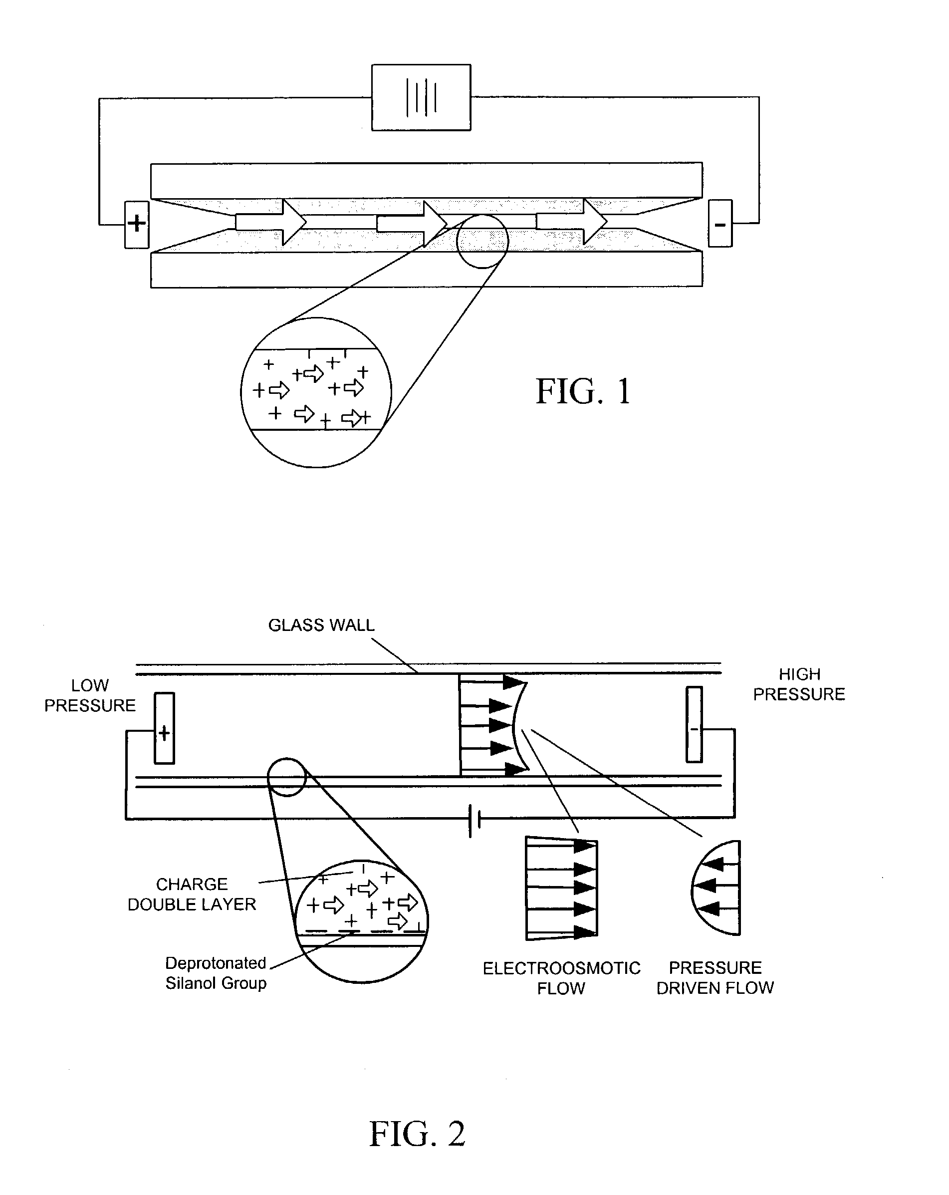
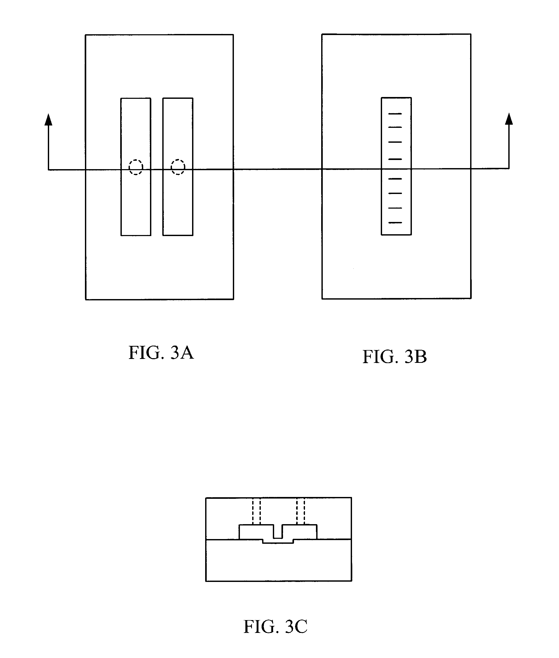
An electroosmotic micropump having a plurality of thin, closely-spaced, approximately planar, transversel aligned partitions formed in or on a substrate, among which electroosmotic flow (EOF) is generated. Electrodes are located within enclosed inlet and outlet manifolds on either side of the partition array. Inlet and outlet ports enable fluid to be pumped into and through the micropump and through an external friction load or head. Insulating layer coatings on the formed substrate limit substrate leakage current during pumping operation.

Description

STATEMENT REGARDING FEDERALLY SPONSORED RESEARCH OR DEVELOPMENT[0001]The invention described herein was supported in part by the DARPA HERETIC program, Air Force Contract F33615-99-C-1442.BACKGROUND OF THE INVENTION[0002]This invention relates generally to non-mechanical micropumps, and more particularly, to electroosmotic micropumps fabricated using microfabrication techniques.[0003]Various types of micropumps have been fabricated using microfabrication techniques. Micropumps can be classified into two categories: mechanical and non-mechanical. Mechanical micropumps such as electrostatically driven reciprocating pumps and thermopneumatically driven peristaltic pumps, contain moving pumps which are of serious concern for long-term reliability. Some of the non-mechanical micropumps, such as electrohydrodynamic micropumps and magnetohydrodynamic, micropumps cannot pump deionized (DI) water due to their fundamental working principles. As a result, these types of non-mechanical micropum...

Claims


Application Information

Patent Timeline
Patent Type & Authority Patents(United States)
IPC IPC(8): H02K44/00F04B37/02F04F11/00H02K44/08F04B17/00F04B19/00F04F99/00
CPCF04B17/00F04B19/006
Inventor GOODSON, KENNETH E.KENNY, THOMAS W.SANTIAGO, JUAN G.LASER, DANIEL J.CHEN, CHUAN-HUA
Owner THE BOARD OF TRUSTEES OF THE LELAND STANFORD JUNIOR UNIV
Why Eureka
Eureka Blog
Learn More