Rotor of motor

a technology of rotor and motor, which is applied in the direction of rotating magnets, magnetic circuit rotating parts, synchronous machines with stationary armatures, etc., can solve the problem of insufficient positional detection by the position sensor

Active Publication Date: 2008-01-08
TOSHIBA LIFESTYLE PROD & SERVICES CORP
View PDF14 Cites 14 Cited by
  • Summary
  • Abstract
  • Description
  • Claims
  • Application Information

AI Technical Summary

Benefits of technology

[0008]In the above-described construction, the position sensor is disposed radially or axially opposite the outer peripheral face or the axial end of the rotor core. Thus, since the position sensor is located away from the stator, adverse effects of the stator to the position sensor can be restrained and the detecting timing of the position sensor can be accurate. Consequently, the operating efficiency of the motor can be improved.

Problems solved by technology

Accordingly, an amount of magnetic flux acting upon the position sensor 107 is so small that the positional detection by the position sensor is insufficient.

Method used


Image

  • Rotor of motor
  • Rotor of motor
  • Rotor of motor

Examples


first embodiment

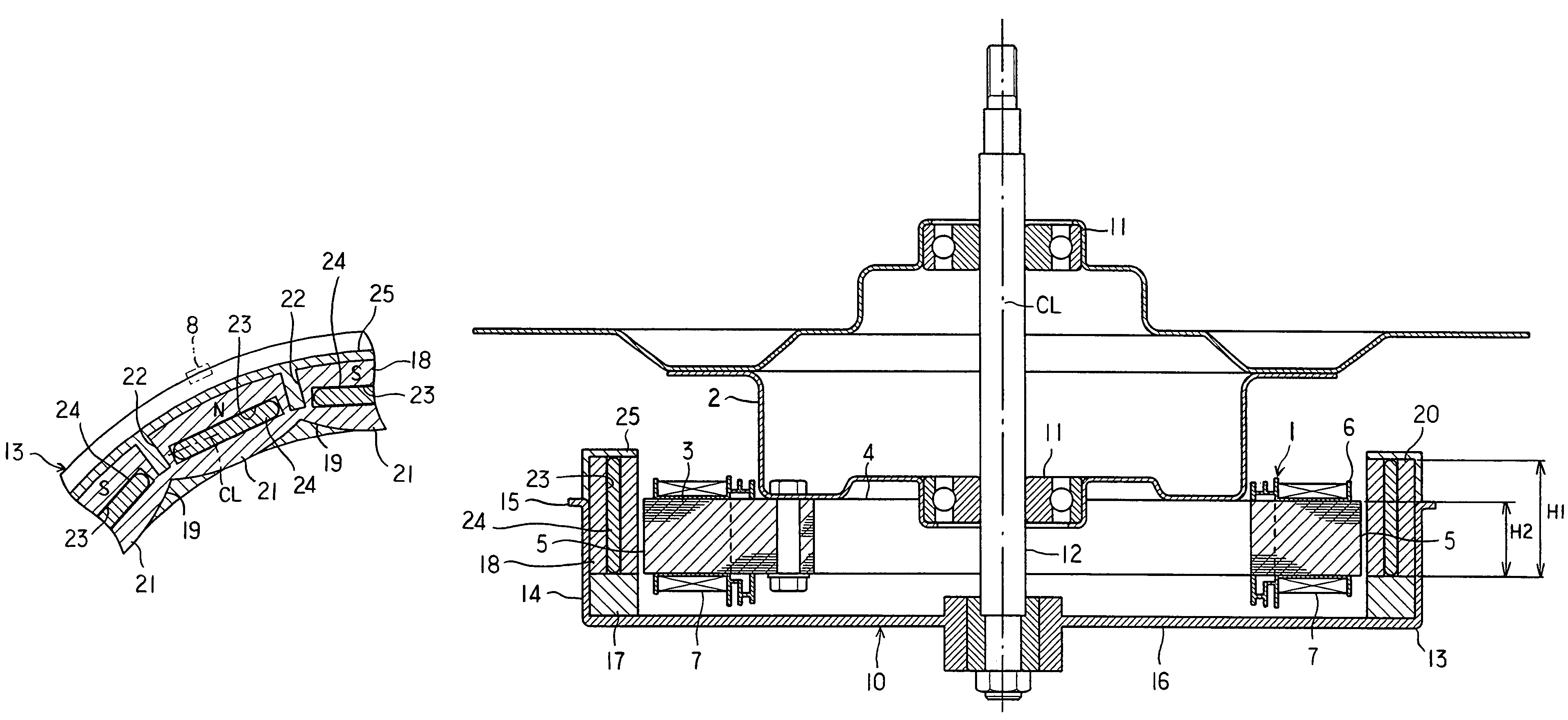
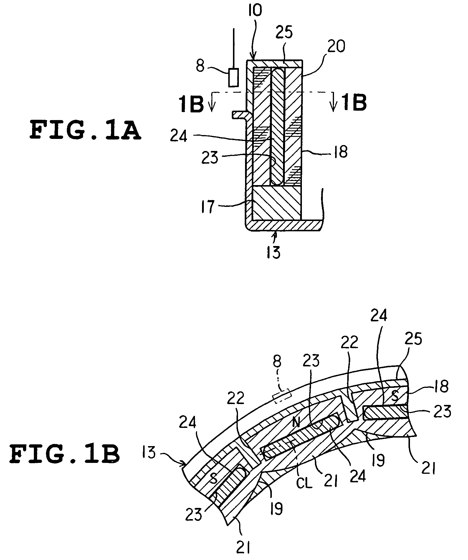
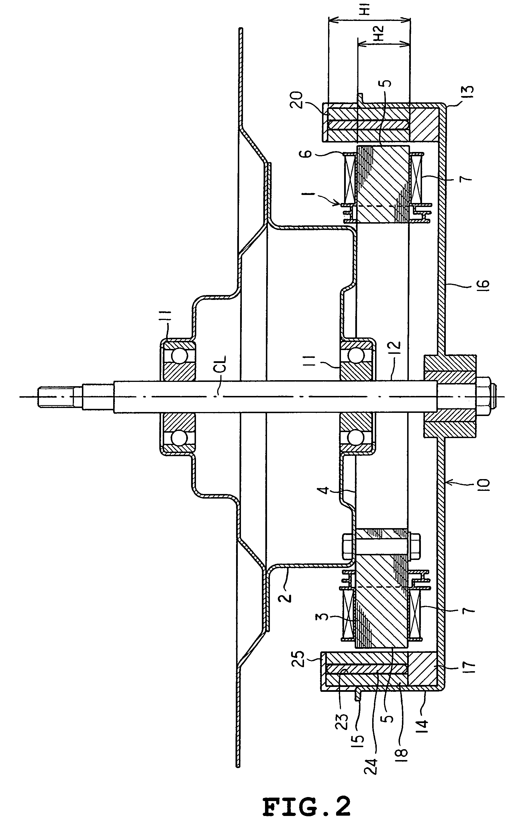
[0023]FIGS. 1A, 1B and 2 show a first embodiment of the invention. Referring first to FIG. 2, a stator 1 includes a base 2 and a stator core 3 screwed to the base. The stator core 3 is formed by axially stacking a number of magnetic steel sheets and includes a generally cylindrical yoke 4 and a plurality of radially extending teeth 5. An insulating layer 6 made of a synthetic resin is formed on a surface of the teeth 5. Phase U, V and W coils 7 are wound on the insulating layer 6. An arm-shaped holder (not shown) extending toward the outer periphery is fixed to the insulating layer 6. A position sensor 8 comprising Hall elements is fixed to the holder as shown in FIGS. 1A and 1B.

[0024]The rotor 10 will now be described. Two outer rings of bearings 11 are fixed to the base 2 as shown in FIG. 2. A rotational shaft 12 is fixed to inner rings of the bearings 11. The rotational shaft 12 extends along a central axis of the stator core 3 and has a lower end to which a rotor frame 13 servin...

second embodiment

[0036]A second embodiment of the invention will be described with reference to FIG. 3. The second embodiment differs from the foregoing first embodiment in the following respects.

[0037]Each rotor magnet 24 has the axial dimension H3 or height set so as to be smaller than the axial dimension H1 of the rotor core 18, as shown in FIG. 3. Each magnet inserting portion 23 has an inner upper end defined with a space 26 where no rotor magnet is provided. Each space 26 is formed with a closure 27 made of a synthetic resin, so that each rotor magnet 24 is confined in the magnet inserting portion 23 by the closure 27. Molten resin is poured into each space 26 in the forming of the core base 17 and the insulating layer 25, so that the closures 27 are formed integrally with the core base and the insulating layer. The position sensor 8 is disposed so as to be spaced away from the closures 27, thereby axially opposing the outer circumferential face of the protrusion 20.

[0038]According to the seco...

third embodiment

[0039]A third embodiment of the invention will be described with reference to FIGS. 4A and 4B. The third embodiment differs from the first embodiment in the following respects.

[0040]A plurality of magnetic walls 28 corresponding to the protrusions are formed on the upper end of the rotor core 18 as shown in FIGS. 4A and 4B. The magnetic walls 28 are adapted to come into contact with the outer circumferential faces of the rotor magnets 24. The position sensor 8 is axially opposed to upper ends of the magnetic walls 28.

[0041]According to the third embodiment, the protrusion-like magnetic walls 28 are formed on the outer circumferential faces of the rotor magnets 24 in the axial end of the rotor core 18. As a result, the magnetic flux tends to reflow circumferentially. Moreover, the magnetic walls 28, rotor magnets 24 and rotor core 18 have the respective upper ends located at different levels. Accordingly, since the magnetic flux for the position sensor 8 tends to axially reflow easil...


PUM


Abstract

A rotor for an electric motor includes a base plate (13) made of a magnetic material and coupled to a rotational shaft (12), a rotor core (18) provided on the base plate (13) and including a protrusion protruding axially relative to the base plate and the teeth of the stator, the rotor core having an outer peripheral face and an axial end, a plurality of magnet insertion portions defined in the rotor core, a plurality of rotor magnets provided in the magnet insertion portions respectively, each magnet having a stator side and a counter-stator side both magnetized so as to have poles differing from each other, and a position sensor detecting a rotational position of the rotor core and disposed radially or axially opposite the outer peripheral face or the axial end of the rotor core so as to correspond to the protrusion of the rotor core.

Description

CROSS REFERENCE TO RELATED APPLICATIONS[0001]This is the U.S. National Phase of PCT / JP2004 / 012559, filed Aug. 31, 2004, which in turn claims priority to Japanese Patent Application No. 2003-340225, filed Sep. 30, 2003, both of which are incorporated herein in their entirety by reference.TECHNICAL FIELD[0002]This invention relates to a rotor for an electric motor of the outer rotor type in which the rotor is provided for rotation around a stator.BACKGROUND ART[0003]Japanese Patent No. 3017953 discloses a rotor for an electric motor of the above-described type. FIGS. 8A and 8B of the present application illustrate the conventional rotor for an electric motor. As shown, the rotor includes a rotor core 102 provided for rotation around a stator 101. The rotor core 102 is fixed to a bed plate 103 made from a magnetic material. The rotor core 102 includes a plurality of magnet insertion sections 104 formed therein. A rotor magnet 105 is fixed to each magnet insertion section 104.[0004]In t...

Claims


Application Information

Patent Timeline
Patent Type & Authority Patents(United States)
IPC IPC(8): H02K1/27H02K1/22H02K21/22H02K29/08
CPCH02K1/2786H02K29/08H02K1/2791H02K11/215H02K1/279H02K21/22H02K15/12H02K15/03
Inventor SHIGA, TSUYOSHI
Owner TOSHIBA LIFESTYLE PROD & SERVICES CORP
Why Eureka
Try Eureka