Linear variable differential transformer with complimentary step-winding secondary coils

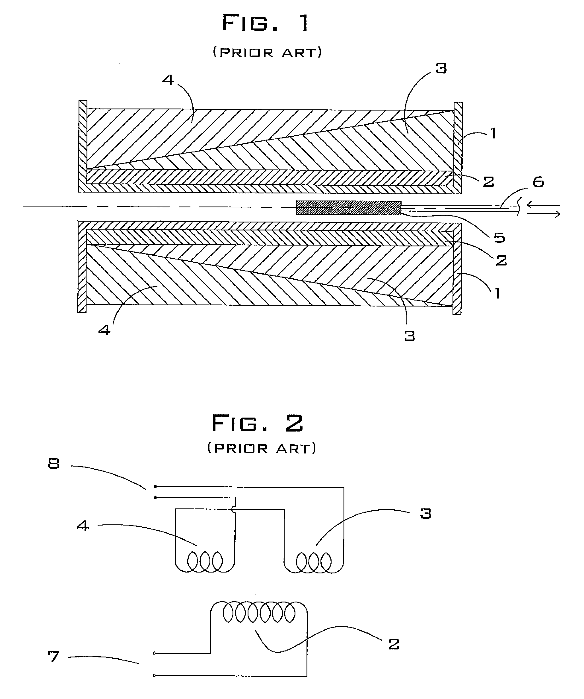
a technology of linear variable differential transformer and secondary coil, which is applied in the direction of continuously variable inductance/transformer, inductance, instruments, etc., can solve the problems of affecting the linear range (or maximum measurement range) of the device for some applications, the core is located physically closer to one of the secondary windings, and the construction of prior art devices is relatively difficul

Inactive Publication Date: 2008-01-08
RHINESMITH R BRET
View PDF18 Cites 24 Cited by
  • Summary
  • Abstract
  • Description
  • Claims
  • Application Information

AI Technical Summary

Problems solved by technology

Prior art devices are relatively difficult to construct and are therefore relatively expensive to manufacture.
There are two practical disadvantages to constructing this embodiment of LVDT.
The first disadvantage (noted in Lipshutz's patent) is that the core is located physically closer to one of the secondary windings than the other.
This arrangement causes the “null point” (i.e., the zero output voltage point) of the core to be physically off-center from the center point of the two secondary coils, which in turn potentially adversely affects the linear range (or maximum measurement range) of the device for some applications.
The second—and more important—disadvantage of this embodiment is the difficulty of manufacturing tapered windings by machine or manually.
It is impractical to produce coils having sufficient taper with the wire diameters required for LVDTs in practical sizes.
Currently available commercial LVDTs do not utilize tapered windings, due to the difficulty of manufacturing such devices.
Lipshutz's second embodiment describes an alternate and more symmetrical tapered winding configuration for the secondary coils that overcomes the null point problem but does not address the difficulty of practical manufacture of the tapered windings.
These connections require additional manufacturing steps and are a potential source of reduced reliability for the device.
There are no edge supports (i.e., ribs) to keep the individual coils separated and properly stacked in this device, and Lipshutz does not describe the methods used to prevent the relatively short, thick coils from collapsing during the winding process without edge supports.
This device utilizes variable-pitch coils and requires relatively complex electronic circuitry, all of which adds to the manufacturing cost.
The tall stack comprised of multiple short layers in the Bauer device would be difficult to construct without having the layers collapse during manufacture.

Method used


Image

  • Linear variable differential transformer with complimentary step-winding secondary coils
  • Linear variable differential transformer with complimentary step-winding secondary coils
  • Linear variable differential transformer with complimentary step-winding secondary coils

Examples


Embodiment Construction

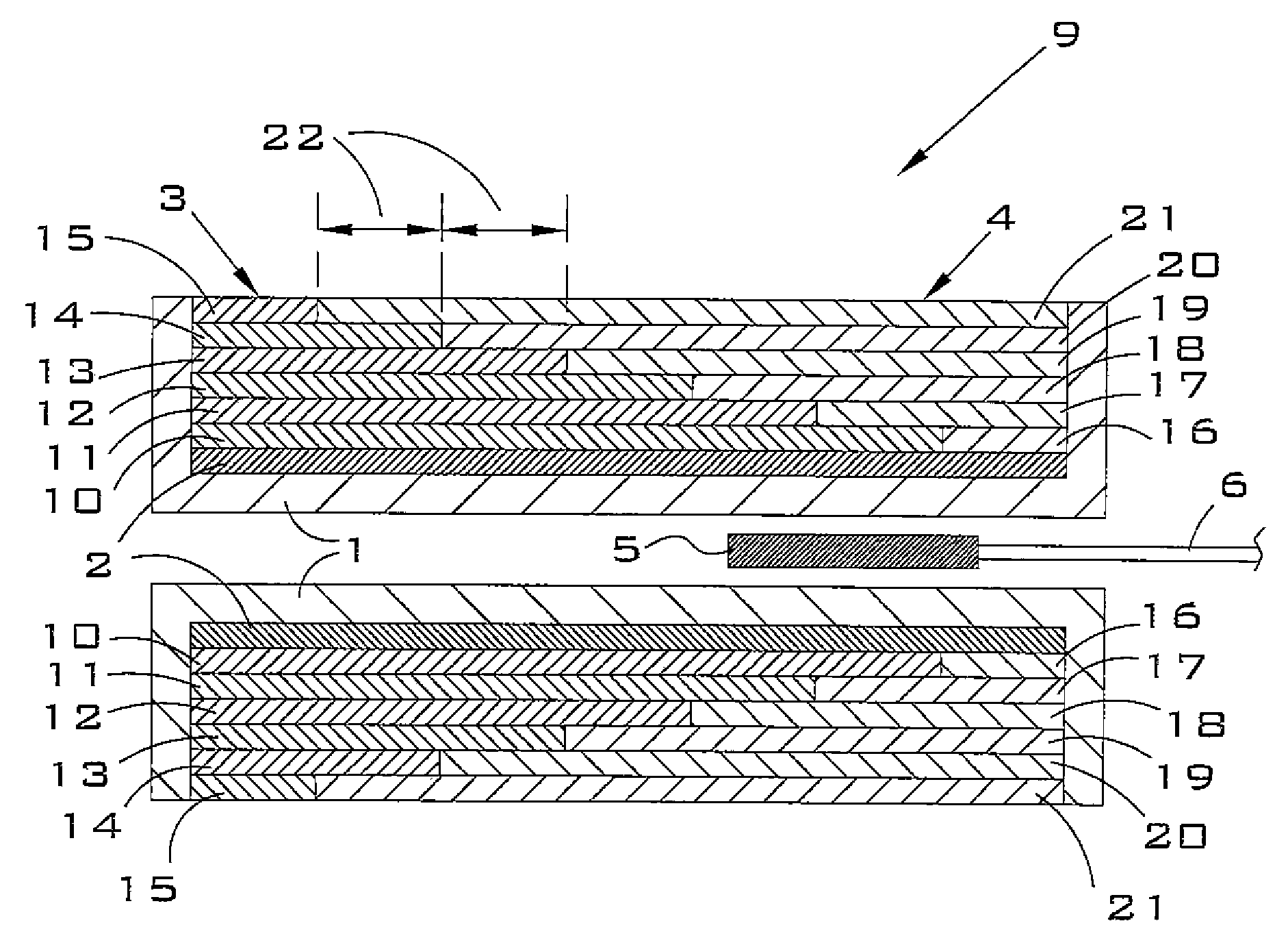
[0055]The present invention overcomes the deficiencies in prior art devices by providing, in a first embodiment, two continuous and complimentary secondary coils that are wound in stepped layers, in contrast to the tapered coils or individual coil segments described in the prior art. This design provides linear output response over a relatively long range of core displacement and requires a minimum number of internal electrical connections. The design is relatively easy to manufacture by either machine or manual methods. The two secondary coils of the present invention are connected in series with matching polarity, as opposed to the prior art of Lipshutz and others whose secondary coils are connected in opposite phase. A center-tap electrical connection is also provided between the two coils so that the voltage of each secondary coil may be measured independently of the other. By this means, it is possible to measure both the sum and difference of the two secondary voltages indepen...


PUM

PropertyMeasurementUnit
diameteraaaaaaaaaa
lengthaaaaaaaaaa
step lengthaaaaaaaaaa

Abstract

A linear variable differential transformer comprising a coil form; a first primary coil; an optional second primary coil; a first secondary coil; and a second secondary coil; wherein the windings of the secondary coils create complimentary and preferably uniform steps. Each step is preferably wound in at least two layers. In the embodiment comprising two primary coils, the inductive couplings between the primary and secondary coils cause null position to be physically centered within the transformer.

Description

BACKGROUND OF THE INVENTION[0001]1. Field of the Invention[0002]The present invention relates generally to the field of electromechanical devices, and more particularly, to a linear variable differential transformer with complimentary step-winding secondary coils.[0003]2. Description of the Related Art[0004]Linear variable differential transformers (LVDTs) are electromechanical transducers that convert rectilinear motions of externally coupled objects into electrical signals that are proportional to the positions of the objects. LVDTs have been utilized in conjunction with a wide range of measurement and control devices such as flowmeters, strain gages, and pressure sensors. Important characteristics of a practical LVDT include (i) the ability to produce a linear output signal over a relatively large displacement range relative to the overall length of the device, (ii) durability and reliability, and (iii) relatively low cost of manufacture.[0005]Numerous techniques have been employ...

Claims


Application Information

Patent Timeline
Patent Type & Authority Patents(United States)
IPC IPC(8): H01F21/06
CPCG01D5/2291H01F29/10
Inventor CARROLL, ANTHONY JUSTIN
Owner RHINESMITH R BRET
Why Eureka
Try Eureka