Vehicle navigation, collision avoidance and control system

a technology of collision avoidance and control system, which is applied in the direction of transmission, electrical equipment, railway components, etc., can solve the problems of the main lobe angular width, the angular resolution of the microwave radar, and the difficulty of making a reasonable size microwave radar with beam width less than 3 degrees, so as to improve the accuracy of gps ranging signals and accurately determine one's position. , the effect of improving the accuracy of the gps ranging signal

Inactive Publication Date: 2008-01-08
NAHLA IBRAHIM
View PDF72 Cites 48 Cited by
  • Summary
  • Abstract
  • Description
  • Claims
  • Application Information

AI Technical Summary

Benefits of technology

[0045]One aspect of the invention is a computer controlled collision avoidance and warning method which includes the steps of receiving continuously from a network of satellites on a first communication link at one of a plurality of trains GPS ranging signals for initially accurately determining the one's position on a track on a surface of the earth; receiving continuously at the one train on a second communication link from one of a plurality of stations having a known fixed position on the surface of the track (track based transponders) for positive track identification and correcting propagation delay errors in the GPS ranging signals and for still further improving the accuracy of the GPS ranging signals and of determining the one's position on a track on a surface of the earth; determining continuously at the one train from the GPS, the one's kinematic tracking position on the surface of the track augmented with neural networks to provide higher accuracy . . . , communicating the one's status information including the kinematic tracking position to each other one of the plurality of trains and to the plurality of train control centres, and receiving at the one train each of the others' of the plurality of train status information including the others' kinematic tracking position; determining in a logic associative memory (LAM) the one's response relative to each collision hazard; generating control signals for actuating an override control mechanism, that interface with train controls, to stop the train / s short of a collision; intelligibly indicating a warning of a collision hazard; and, co-ordinately actuating the real-time logging of train characteristics in real time sufficiently in due time to avoid each collision hazard;
[0046]The present invention provides moving train collision avoidance, warning and control systems and methods using GPS satellite location systems augmented with neural networks to provide higher location accuracy, and to derive train attitude and position coordinates and one's kinematic tracking information. Ground based controller computers are used to communicate with trains for the purpose of receiving location and train status information and broadcasting control information to respective trains, such GPS location and computing systems being integrated with track transponders scanning and on-board Train Navigation Unit (TNU) to provide accurate train location information together with information concerning impending collision situations for each train. The present invention and method disclosed herein will measure beneficially high in Safety and Environmental areas and will make the train controllers in more control and the train operators, proactive rather reactive.
[0049]Yet, a further enhancement of the Train Navigation and Control System (TNCS) and method disclosed herein makes use of a real-time logging of train characteristics system to record the last several minutes of driving action for future analysis. Such recordings permit reconstruction of events leading up to collision permitting more accurate determination of causes including fault.
[0105]Each fixed transponder station emits correction signals for correcting errors in GPS ranging signals from the first communications link; wherein the correction signals allow further correction measurements for improving the accuracy of the GPS ranging signals The method comprises the further step of providing a central controller for monitoring vehicle locations and capable of transmitting an override signal to vehicles to actuate a collision avoidance feature. According to one embodiment, the method comprises the further step of processing positions of each vehicle received and / or transmitted to each vehicle via a neural network; wherein the neural network identifies and evaluates each potential collision hazard of one train relative to another train.
[0110]b) ranging signals for initially accurately determining a train position on a rail track,

Problems solved by technology

There are multiple disadvantages of these automobile collision avoidance systems when microwave radars are used.
One major disadvantage is related to the beam width, that is the angular width of the main lobe of the radar, and the associated angular resolution of the microwave radar.
With the limitation of the antenna size, it is very difficult to make a reasonable size microwave radar with beam width less than 3 degrees.
At the desired scanning distance, this beam width will scan an area that is much too big and thus is too nonspecific and difficult to differentiate the received echoes.
On highways with divided lanes the microwave radar will receive echoes from cars 2 or 3 lanes away and has difficulty to in differentiating them from echoes coming from objects in the same lane.
Because of the poor angular resolution of microwave radars, the direction of objects cannot be specifically determined and objects too close to one another cannot be separated.
The angular resolution of microwave radars is not small enough for them to be effectively used to monitor roadway traffic.
The other disadvantage is that the microwave radars have difficulty in distinguishing radar signals coming from adjacent cars with similar equipment.
If there are more than two cars with the same radar equipment on the same scene, the signals become very confusing.
If the rain or snow etc. are heavy enough, they may reduce the effective range of the laser radar.
The first exception is that confusion may occur when an oncoming vehicle's laser beam happen to aim at the system-equipped vehicle's receiver.
A second exception is that confusion may occur when an adjacent vehicle's laser beam happens to illuminate at the same spot as the spot illuminated by the system-equipped vehicle's laser beam.
Aside from that, it suffers from all the disadvantages of radar systems as described above.
In particular, it is not capable of giving accurate three-dimensional measurements of an object on the roadway.
The prior art has failed to integrate some of the known technologies in a comprehensive fashion to provide a complete collision warning and avoidance system.
However, the GPS reception is not to the best of the applicant's knowledge used for automatic accurate recalibration of current vehicular positioning.
These Intelligent Vehicle Highway Systems use the compass and wheel sensors for vehicular positioning for route guidance, but do not use accurate GPS and inertial route navigation and guidance and do not use inertial measuring units for dynamic vehicular control.
Even though dynamic electronic vehicular control, for example, anti-lock braking, anti-skid steering, and electronic control suspension have been contemplated, these systems do not functionally integrate these dynamic controls with an accurate inertial route guidance system having an inertial measuring unit well suited for dynamic motion sensing.
This system provides vehicle to vehicle communications but does not provide a system which allows a vehicle to determine its location relative to fixed positions on a road or track.
That system also suffers from the disadvantage of data storage problems due to unlimited data to be uploaded and stored including road edge detail for every edge for every road and from each angle and direction.
This is impractical to implement and fails to address any changes in road configurations i.e.: new structures like new round abouts or new road islands or emergency works such as excavations and / or road maintenance.
Also this known system does not distinguish navigation under bridges or multiple store roads or tunnels.
Naturally, since radar cannot accurately determine this area it has to be assumed by the system.
In addition to the clock error, the atmospheric error and errors from selective availability, other errors which affect GPS position computations include receiver noise, signal reflections, shading, and satellite path shifting (e.g., satellite wobble).
These errors result in computation of incorrect pseudoranges and incorrect satellite positions.
Incorrect pseudoranges and incorrect satellite positions, in turn, lead to a reduction in the precision of the position estimates computed by a vehicle positioning system.
Thus, true collision avoidance cannot be obtained without an accurate knowledge of the road geometry.
Search techniques often require significant computation time and are vulnerable to erroneous solutions or when only a few satellites are visible.
If carried to an extreme, a phased array of antennas results whereby the integers are completely unambiguous and searching is unnecessary.
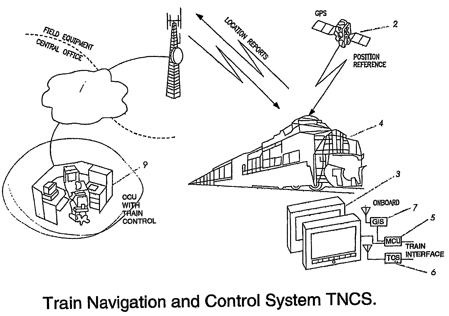
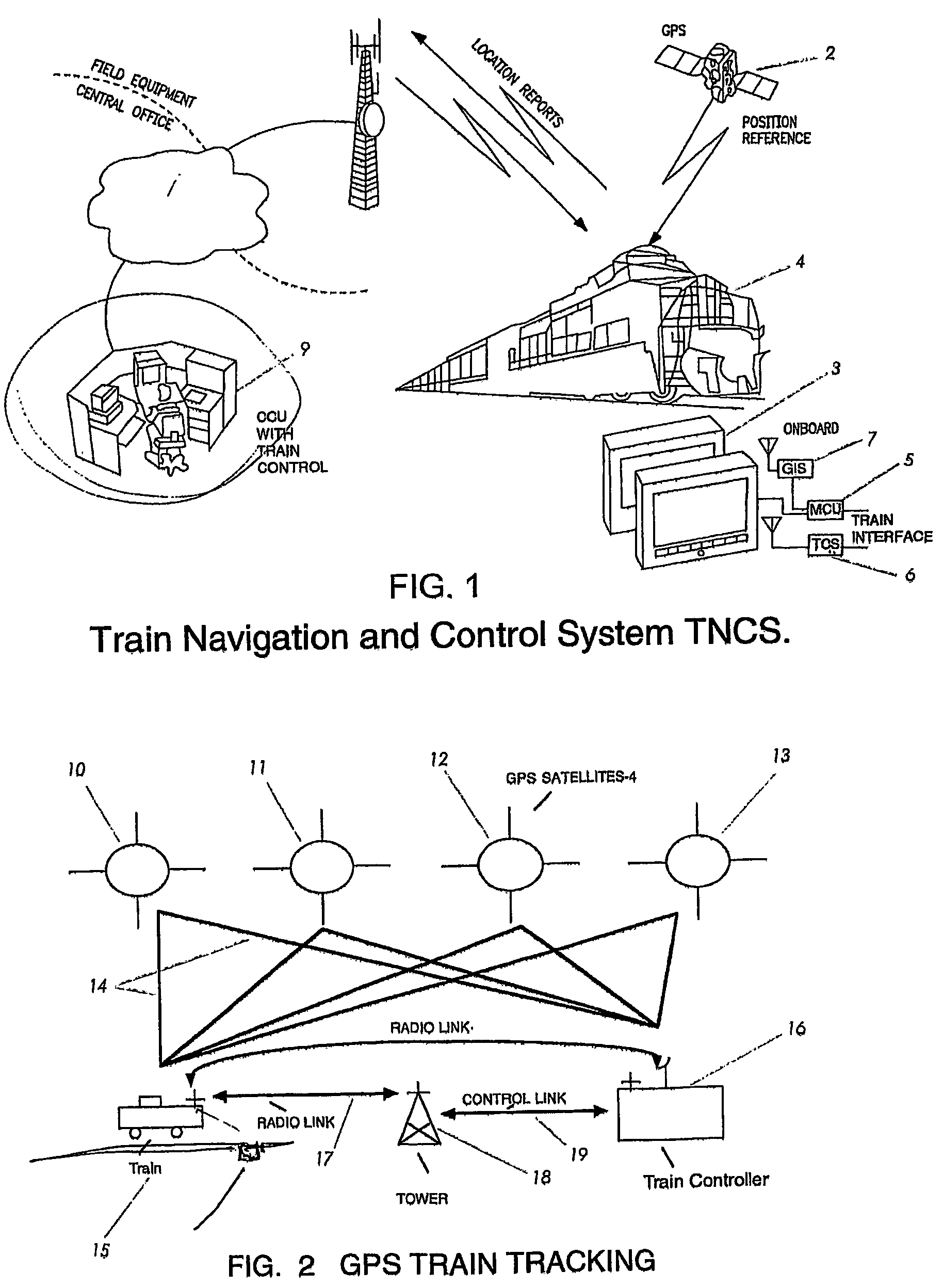
Rail disasters in recent years have highlighted that the current state of the rail networks is no longer accepted worldwide.
Train accidents are one of the most serious problems faced by our society, both in terms of personal deaths and injuries, and in financial losses suffered as a result of accidents.
Human suffering caused by death or injury from such accidents is immense.
In addition, the costs of medical treatment, permanent injury to accident victims resulting in loss of life opportunities, and financial losses resulting from damage to trains and other valuable objects or structures involved in such accidents are staggering.
However, these systems fail to provide such back-up scanning and multiple target detection and tracking as part of an integrated GPS collision avoidance and warning system capable of multiple target, logic, higher accurate, train-on-the-track, operational environment.

Method used


Image

  • Vehicle navigation, collision avoidance and control system
  • Vehicle navigation, collision avoidance and control system
  • Vehicle navigation, collision avoidance and control system

Examples


Embodiment Construction

[0158]The present invention in one broad form provides a computer controlled collision avoidance and warning system in which signals are received by at least one vehicle on a first communication link from a GPS satellite link for determining the position of that vehicle. The invention further provides a second communications link in which at least one of a plurality of vehicles receive continuously a signal concerning the position of at least one other vehicle so that each vehicle known the position of another vehicle so that evasive action may be taken in the event of a collision. The first communications link is a GPS receiver and the second communications link is a GPS transceiver each operating on separate predetermined frequencies. (see FIG. 2).

[0159]Although the present invention will be described with reference to its application to train collision warning it will be appreciated by persons skilled in the art that the invention has applications for vehicle collision management...


PUM


Abstract

A collision warning and avoidance system which comprising an integrated on-board Train Navigation Unit (3) and a GPS Interface Subsystem to locate a train. The system includes a GPS (2) location signal, at least one fixed transponder station (31) and a calibrated, rectified transponder identification subsystem for scanning the track based transponders for override of train controls in the event of a collision risk and further comprising a database of all transponders, their location and the track ID on which they are located. Data and information are computer processed and analysed in neural networks in one train to identify, rank, and evaluate collision hazards.

Description

[0001]This application is a 371 U.S. national stage application of international application PCT / AU03 / 00342 filed on Mar. 21, 2003, which claims priority of Australian patent application PS 1237 filed on Mar. 22, 2002.BACKGROUND[0002]The present invention relates to vehicle safety and more particularly relates to an identification system capable of vehicle collision warning and avoidance and More particularly the invention relates to collision avoidance systems for track networks including means to allow vehicle and track identification. More particularly the present invention relates to anticipatory detection and transmission of a vehicle location in a network for the purpose of avoidance of a collision between two or more vehicles in the network. Although the invention to be described herein is adaptable to a variety of vehicle networks, it will primarily be described with reference to its application to rail cars in rail networks.PRIOR ART[0003]There are in existence a variety of...

Claims


Application Information

Patent Timeline
Patent Type & Authority Patents(United States)
IPC IPC(8): G06F17/10G01S19/14B61L23/00B61L25/02B61L27/00G01C21/28G01S19/49G08G1/16H04B7/185
CPCB61L25/021B61L25/023B61L25/025B61L27/0038G08G1/164B60T2201/022B61L2205/04B61L15/0072B61L27/20
Inventor NAHLA, IBRAHIM
Owner NAHLA IBRAHIM
Why Eureka
Try Eureka