
Vehicle positioning apparatus

a vehicle positioning and correct positioning technology, applied in the direction of optical apparatus testing, instruments, force/torque/work measurement, etc., can solve the problems of increasing the number of components in the apparatus as a whole, difficult to achieve accurate positioning, and inconvenient operation of conventional vehicle positioning apparatuses for such high precision optical axis adjustment. achieve the effect of high efficiency and high accuracy

Inactive Publication Date: 2008-01-15
TOYOTA JIDOSHA KK
View PDF14 Cites 6 Cited by
  • Summary
  • Abstract
  • Description
  • Claims
  • Application Information

AI Technical Summary

Benefits of technology

Enables high-precision positioning of vehicles with different configurations using a single apparatus, preventing elastic deformation and hysteresis, and allowing continuous handling of various types with improved efficiency.

Problems solved by technology

As a result, elastic deformation or histeresis occurs in and around the legs of the vehicle, making it difficult to achieve accurate positioning.
Therefore, conventional vehicle positioning apparatuses are not suitable for such high precision optical axis adjustment, and there is a need for a positioning apparatus having higher positioning accuracy.
Another problem associated with the conventional vehicle positioning apparatuses is that, when vehicles with different wheel tracks, tire sizes, or wheelbases are to be positioned with high precision, optimum equipment must be separately provided for each type of vehicle, which would increase the number of components in the apparatus as a whole.

Method used


Image

  • Vehicle positioning apparatus
  • Vehicle positioning apparatus
  • Vehicle positioning apparatus

Examples


Embodiment Construction

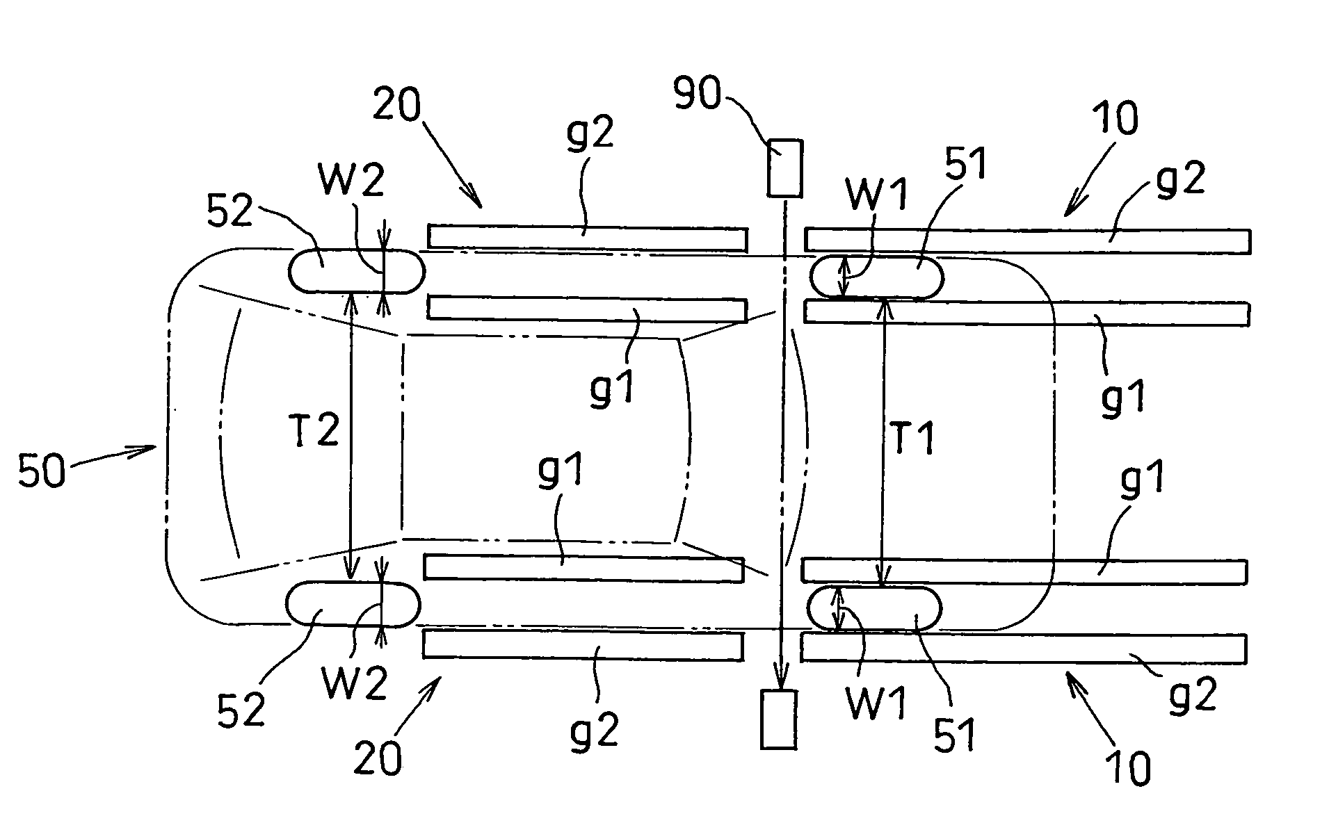
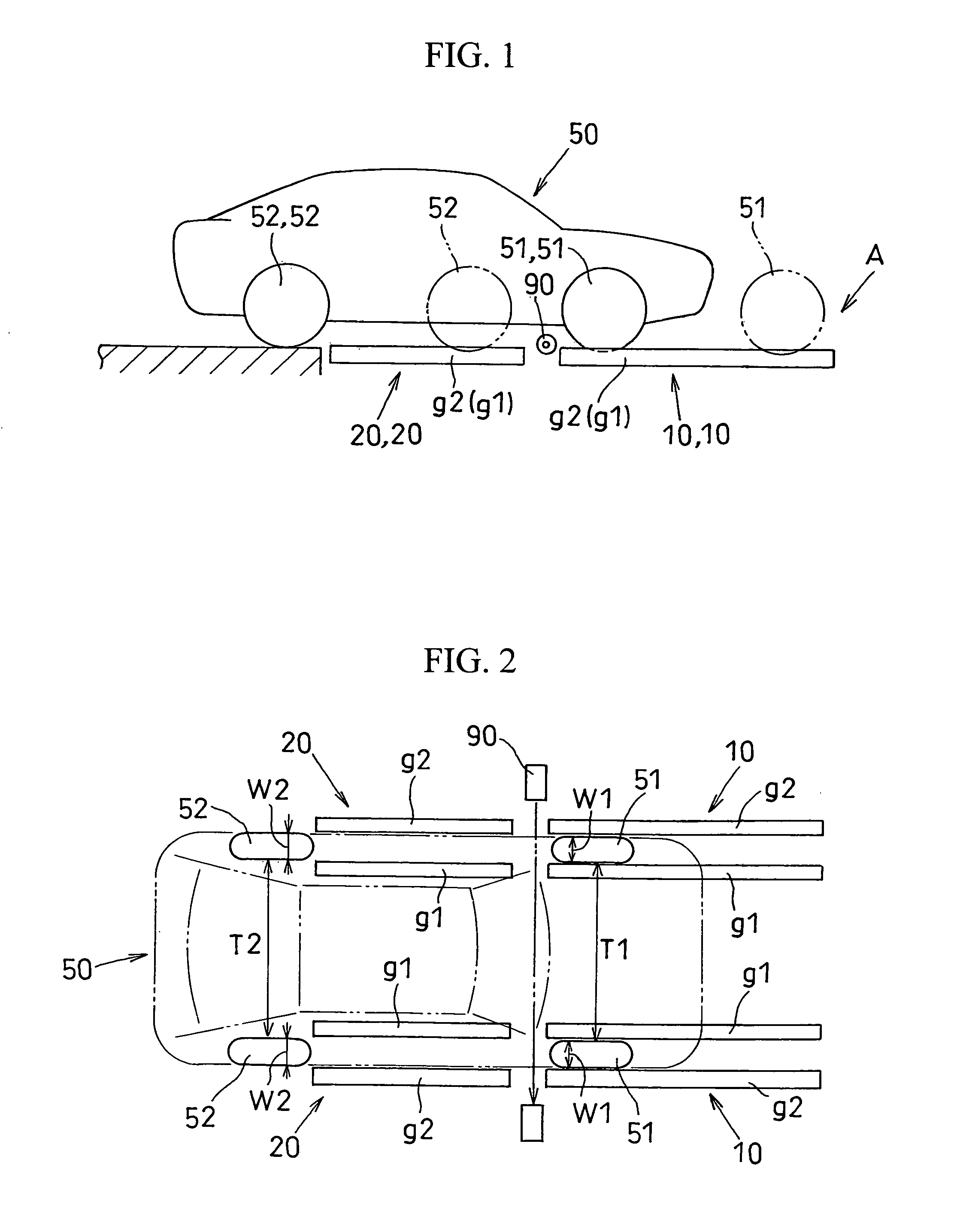
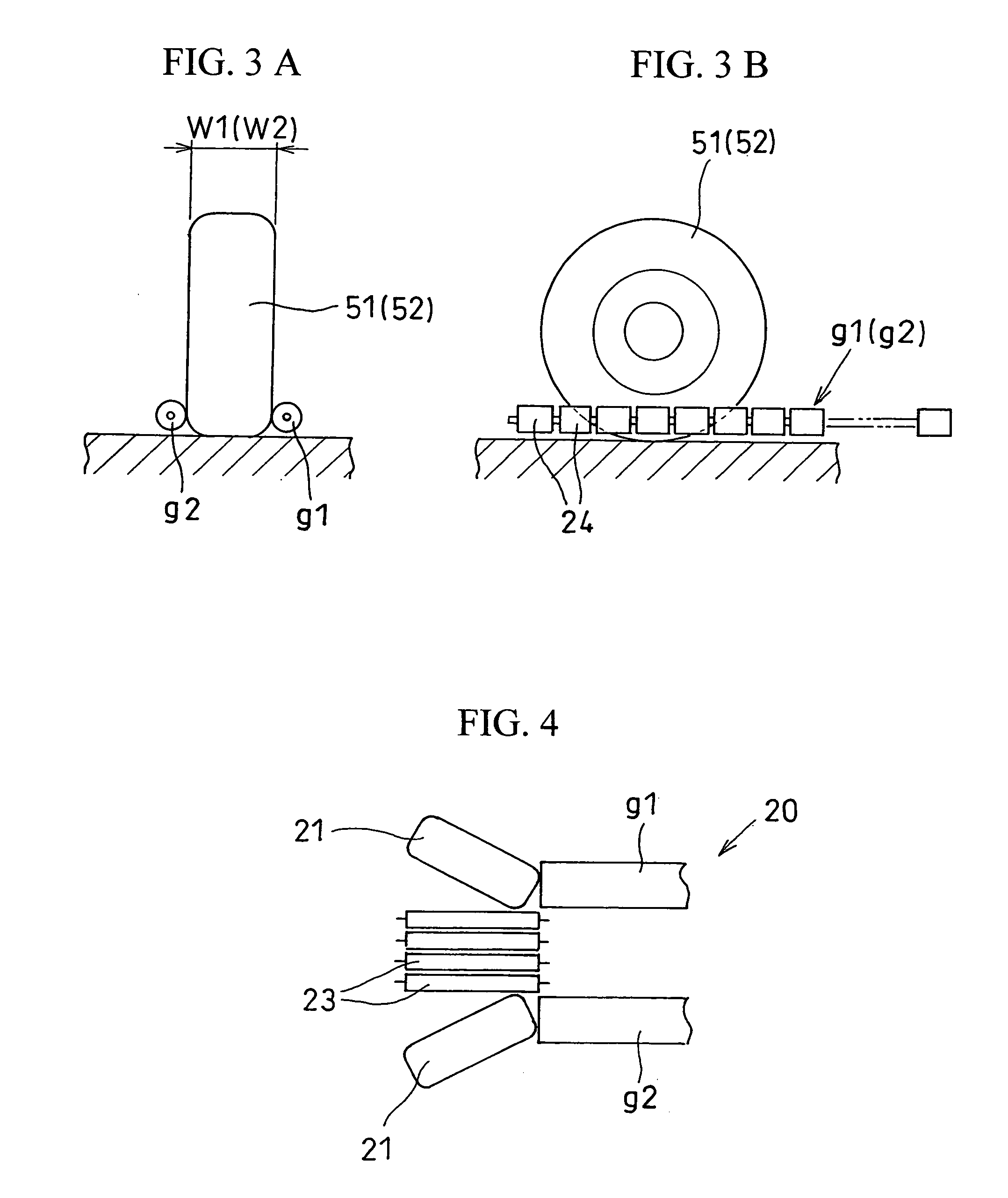
[0034]The embodiments of the invention will be hereafter described with reference to the drawings. FIG. 1 shows a schematic side view of a vehicle, with reference to which the vehicle positioning apparatus of the invention will be described. FIG. 2 shows a schematic plan view. FIG. 3 shows vehicle tires as they are held on either side thereof using the vehicle positioning apparatus. FIG. 3(a) shows a front view, and FIG. 3(b) is a side view. FIG. 4 shows a mode of operation on the vehicle-entry side of a rear-wheel guide unit. FIG. 5 shows an example of an adjustment mechanism in each of a plurality of wheel guide units of which the vehicle positioning apparatus is comprised. FIG. 6 shows another example of the adjustment mechanism in each wheel guide unit. FIG. 7 shows an example of a control unit. FIG. 8 shows an example of a control flowchart.

[0035]A vehicle positioning apparatus A illustrated in the drawings includes two wheel guide units 10 for the front wheels, and two wheel g...


PUM


Abstract

A vehicle positioning apparatus capable of avoiding the elastic deformation of the tires or the development of histeresis in and around the legs allows a vehicle to be positioned with high accuracy. The apparatus includes two front wheel guide units 10 and two rear wheel guide units 20, each including a pair of guide members g1 and g2 with a predetermined length that extend in parallel while an interval is maintained between the guide members in accordance with the tire widths W1 and W2 of front wheels 51 and the rear wheels 52, respectively, of a vehicle 50 to be positioned. A correct position of the vehicle can be ensured as the vehicle travels along the wheel guide units with each of the tires restrained by each pair of guide members g1 and g2 on either side of the tire. The apparatus also includes a mechanism for adjusting each of the wheel guide units in accordance with the wheel tracks T1 and T2 of the vehicle 50, whereby various types of vehicles can be handled with a single apparatus.

Description

CROSS REFERENCE TO RELATED APPLICATION[0001]This application is based upon and claims the benefit of priority from prior Japanese Patent Application No. 2004-320792, filed Nov. 4, 2004, the entire contents of which are incorporated herein by reference.BACKGROUND OF THE INVENTION[0002]1. Field of the Invention[0003]The present invention relates to an apparatus for correctly positioning a vehicle during inspection of positioning of the vehicle.[0004]2. Background Art[0005]When the direction of headlights or the optical axis of a rear-guide monitor or the like of a vehicle are checked, the vehicle must be correctly positioned with respect to a predetermined reference line using a vehicle positioning apparatus. Patent Document 1 discloses an apparatus for evaluating one-sided shifting of vehicles using a vehicle positioning apparatus. In this example of prior art, a vehicle to be inspected is transported to a free table (consisting of a pair of rollers or the like) and stopped thereon. ...

Claims


Application Information

Patent Timeline
Patent Type & Authority Patents(United States)
IPC IPC(8): G01M17/00
CPCG01M11/067G01M17/0074
Inventor SUITA, KAZUTSUGU
Owner TOYOTA JIDOSHA KK
Learn More