Fine-pitch anti-wicking terminals and connectors using same

a terminal and fine pitch technology, applied in the direction of connections, electrical appliances, printed circuits, etc., can solve the problems of increasing contact resistance, small gap between the terminals, and space constraints, and achieve the effect of suppressing the flow of fused solder

Inactive Publication Date: 2008-01-15
MOLEX INC
View PDF12 Cites 9 Cited by
  • Summary
  • Abstract
  • Description
  • Claims
  • Application Information

AI Technical Summary

Benefits of technology

[0008]Problems such as these are addressed with advantageous results by the present invention. In this regard, it is an object of the present invention to provide a technology by which a connector having coaxial cables and a large number of terminals arranged at a narrow-pitch are solder-connected together. By this technology, the strength of a fillet formed during the soldering connection between the terminals and the coaxial cables can be secured while preventing the fused solder from flowing out from a soldering region where soldering is to be performed on the terminals, whereby, in the narrow-pitch connector, proper soldering is effected between the terminals and the cables, and further, even when the amount of fused solder is so large as to cause the fused solder to flow to the portion of the terminals which comes into contact with the mating terminals, it is possible to effectively suppress such flow of fused solder.
[0010]The terminal of the present invention is provided with such a depression, whereby the fused solder is received within the depression without spreading, forming the fillet. Accordingly, there is relatively little spreading of the fillet over the terminal surface as compared with the conventional terminals having no such depression in the soldering region. Due to the formation of the fillet within the depression, the volume of the fillet formed between the terminal and the cable increases. Further, when the soldering region of the terminal is formed to be larger in the width direction thereof than the other area of the terminal, thereby defining a stepped portion having a step formed at a boundary portion between the stepped portion and the other area, the fused solder spreads toward and around the periphery of the stepped portion, whereby the fused solder is prevented from unnecessarily spreading to the other area as compared with the case where no such stepped portion is formed.
[0011]In an important aspect of the invention, the strength of the connection force with which the conductor is connected to the terminal through the fillet can be maintained even when the fillet is reduced in width dimension. Therefore the spacing between the terminals can be reduced while maintaining the connection force between the terminal and the cable as it is. As a result, in a fine-pitch connector having a large number of terminals arranged in parallel, the dimension of the connector can be reduced in the direction in which the terminals are arranged in parallel. Further, even when the amount of fused solder is large, it is possible to effectively suppress the flow of fused solder to the portion of the terminal which comes into contact with the mating terminal.

Problems solved by technology

When soldering a large number of coaxial cables to terminals, space constraints are encountered.
However, even when a gap is secured between adjacent terminals, the gap between the terminals must be small when the terminal itself is small.
Further, when the fused solder flows to reach even a portion of the terminal which comes into contact with the terminal of an associated mating connector paired with the connector, contact resistance increases due to the fused solder thus intervening between the two connectors, and this may become a factor for poor contact reliability between the connector and the mating connector.
However, such a manufacturing process using over-molding is extremely difficult in cases involving a narrow pitch of 0.3 mm or less.
Meanwhile, the need for miniaturization has been increasing over the years, which means that the outer dimensions of connectors cannot be increased.

Method used


Image

  • Fine-pitch anti-wicking terminals and connectors using same
  • Fine-pitch anti-wicking terminals and connectors using same
  • Fine-pitch anti-wicking terminals and connectors using same

Examples


Embodiment Construction

[0052]As required, detailed embodiments of the present invention are disclosed herein; however, it is to be understood that the disclosed embodiments are merely exemplary of the invention, which may be embodied in various forms. Therefore, specific details disclosed herein are not to be interpreted as limiting, but merely as a basis for the claims and as a representative basis for teaching one skilled in the art to variously employ the present invention in virtually any appropriate manner.

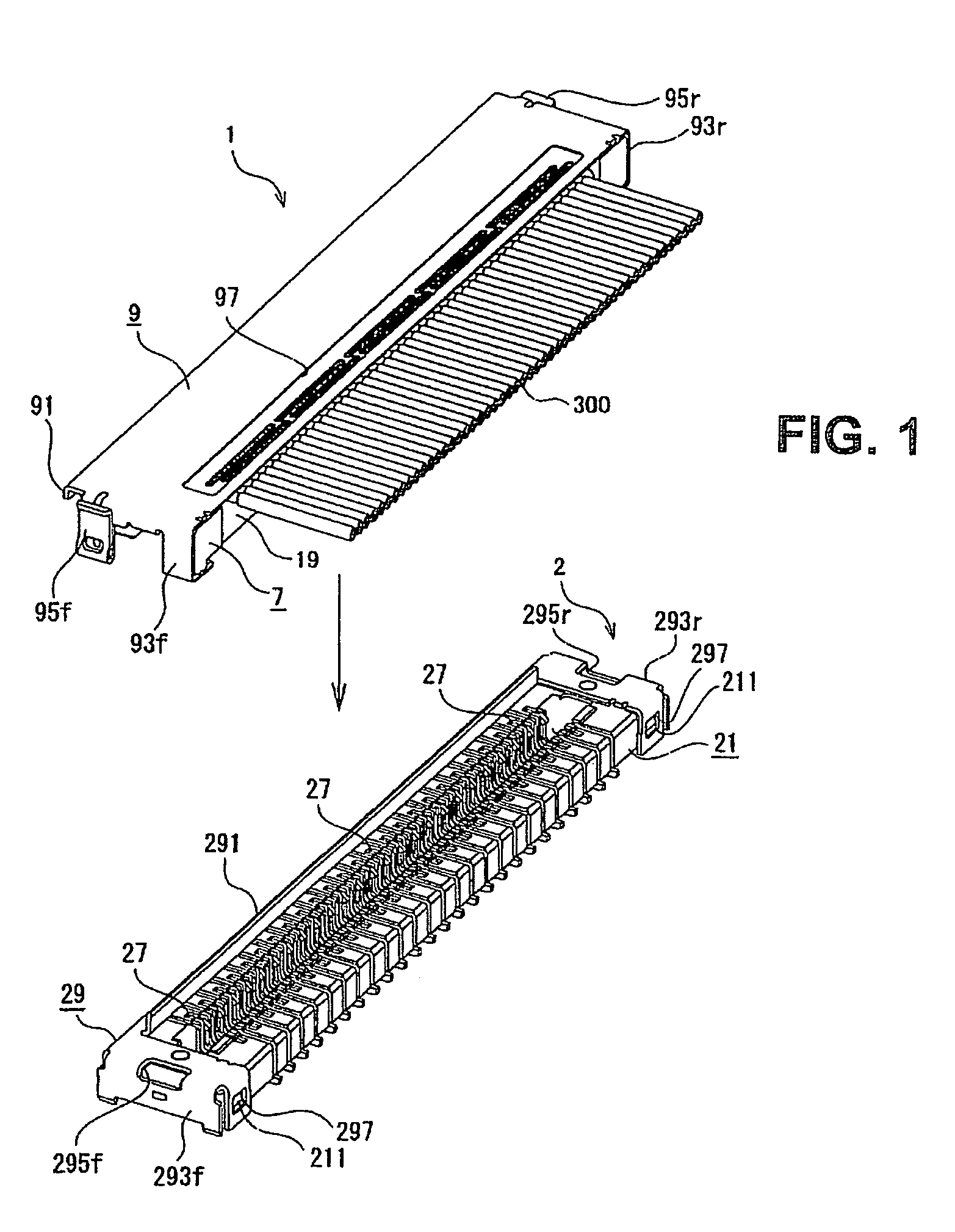
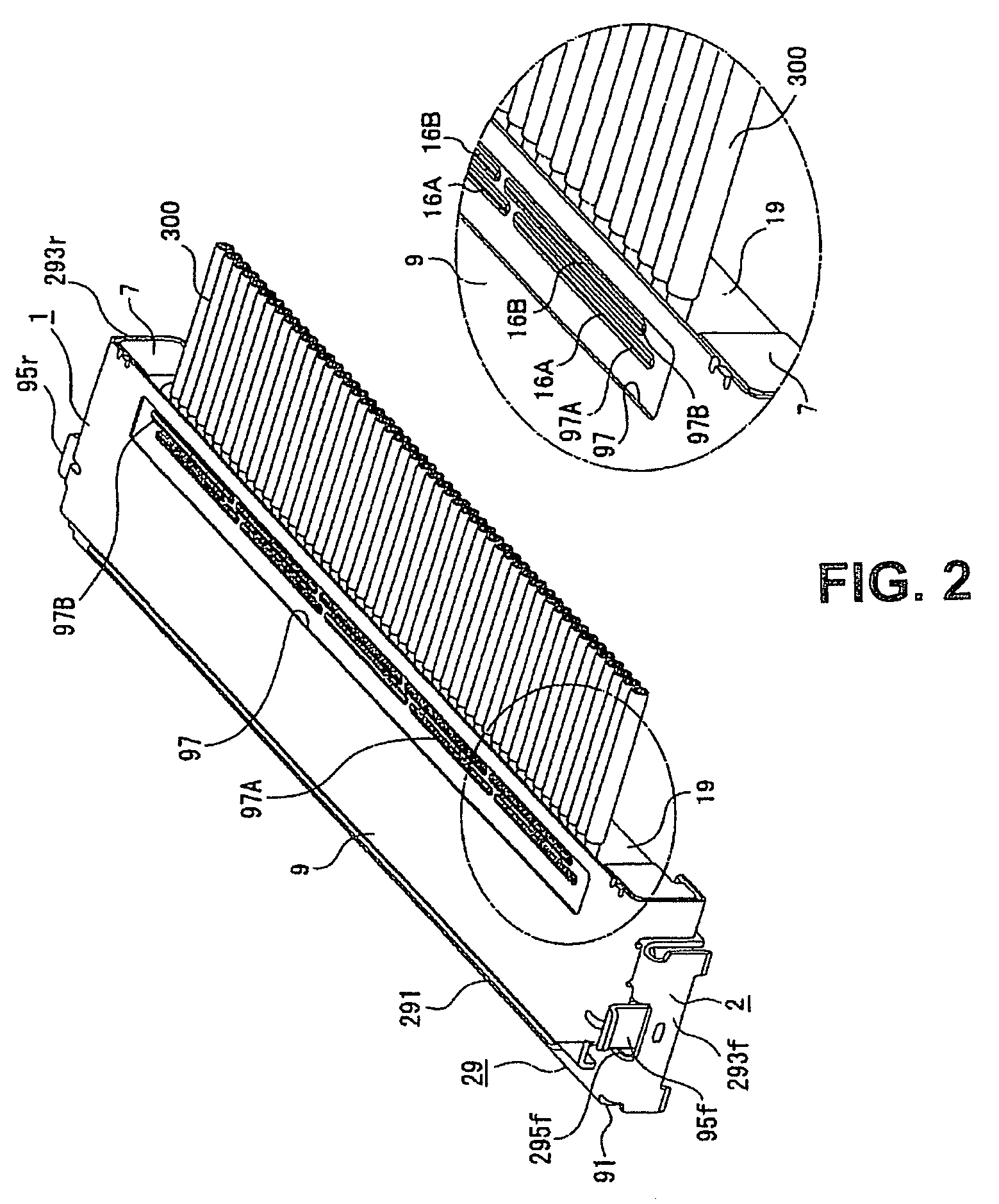
[0053]FIG. 1 is a perspective view illustrating, together with a mating connector 2, a connector 1 according to the present invention in a state prior to its mounting to the mating connector 2. Further, FIG. 2 is a perspective view of the connector 1 as mated with the mating connector 2. It is to be noted that, although not shown in FIG. 2, the connector 1 is also attached to the other end portion of a coaxial cable 300 for mounting to the mating connector 2. FIG. 3 illustrates an example where the...


PUM


Abstract

A fine-pitch terminal and connector reduces the size of a connector in a direction in which a large number of terminals are arranged in parallel. A terminal is applied to a connector, to which a cable having a conductor covered with an insulator is attached, the terminal being connected to the conductor of the cable by soldering. The terminal has a soldering region which is provided in a part of the terminal and to which the conductor of the cable is soldered, and the soldering region has a depression for receiving a fillet.

Description

BACKGROUND OF THE INVENTION[0001]The present invention relates to a terminal and a connector using the terminal. The terminal is for fine-pitch uses and has an anti-wicking feature to control the flow of molten solder during assembly.[0002]Coaxial cables are known as cables for transmitting high-frequency signals in portable telephones, personal computers, and the like in order to transmit a large volume of information. As shown in FIGS. 37 and 38, a typical coaxial cable 300 is composed of a signal line 306 having a centrally located inner conductor 302 covered with an inner insulator 304, an outer conductor 308 consisting of a large number of spirally wound or braided electric wires and covering the signal line 306, and an outer insulator 310 covering the outer conductor 308.[0003]A soldering method, a pressure welding method, and other connection methods are employed in the prior art for connecting the coaxial cable 300 to a connector. When soldering is employed for effecting thi...

Claims


Application Information

Patent Timeline
Patent Type & Authority Patents(United States)
IPC IPC(8): H01R12/00
CPCH01R4/024
Inventor MIYAZAKI, TATSUYA
Owner MOLEX INC
Why Eureka
Try Eureka