Assembly of devices

a technology of devices and components, applied in the field of devices, can solve the problems of large amount of waste heat generated, and achieve the effect of easy adaptation to changing cooling demands

Inactive Publication Date: 2008-01-15
RITTALWERK RUDOLF LOH GMBH & CO KG
View PDF14 Cites 53 Cited by
  • Summary
  • Abstract
  • Description
  • Claims
  • Application Information

AI Technical Summary

Benefits of technology

[0005]It is one object of this invention to provide a device arrangement of the type mentioned above but which can be easily adapted to changing cooling demands.
[0007]The receiving chamber of the cooling device is embodied such that it can be modularly equipped with one or several heat exchanger units. Thus the cooling device can be individually matched to increasing demands. The receiving chamber of the air-conditioning device is vertically divided. In this case zones can be formed as required, by which cooling areas, which are analogously placed on top of each other, can be created in the interior of the switchgear cabinet. It is thus possible to prevent areas of a high thermal level being created by rising heat.
[0008]A defined air guidance can be simply achieved if on their side facing the switchgear cabinet, the partial receiving chambers are closed by a cover. The cover forms the air inlet and the venting opening, and a sealing element arranged on the outside of the cover in the area between the air inlet and the venting opening prevents a short circuit of the air.
[0009]If the cooling module has a heat exchanger unit and at least one fan unit as separate components, the cooling module can be easily manipulated. This is particularly advantageous in case of tight spaces. For example, a walkway of a width of only 80 cm is formed between switchgear cabinets in computer centers. With this invention the cooling module can be easily put together from its components in the partial receiving chambers.
[0010]A stable construction of the cooling devices results if the cooling device has a rack put together from horizontal and vertical profiled frame elements, wherein the profiled frame elements are connected with each other in the corners of the rack. Component floors are horizontally fastened on the rack for dividing the partial receiving chamber, and each cooling module can be placed on the compartment floors. If the cooling module or the partial components have a structural width which is less than the clear opening dimension between the two vertical profiled frame elements at the front of the rack, then the cooling module can be installed from the front of the device and / or the rear. This is of particular advantage if there is no, or only insufficient, lateral access to the cooling device provided because of limited space.
[0013]In one embodiment of this invention, the cooling device has a feed and a return line, through which coolant can be conveyed, and the heat exchanger units can be connected to the feed and the return lines. The feed and return lines can be connected, for example, to an external re-cooling installation. The supply of the heat exchanger units with cooling output is thus solved in a simple way.

Problems solved by technology

Thus, a larger amount of waste heat is generated, which must be removed.

Method used


Image

  • Assembly of devices
  • Assembly of devices
  • Assembly of devices

Examples


Embodiment Construction

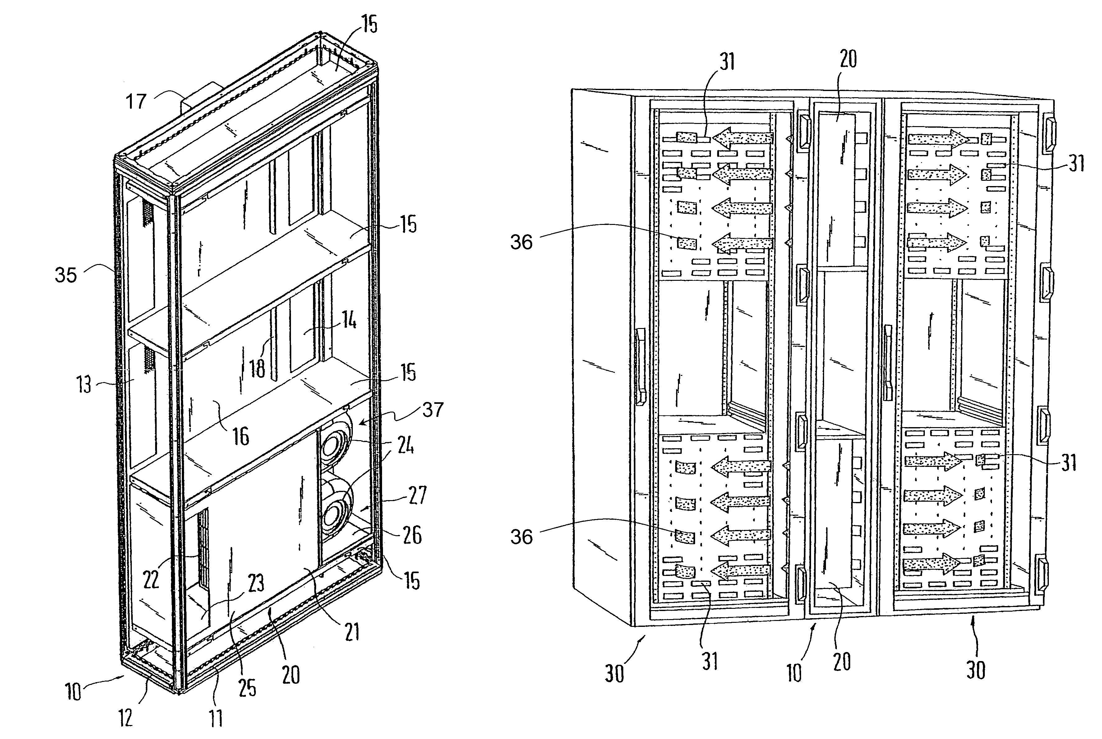
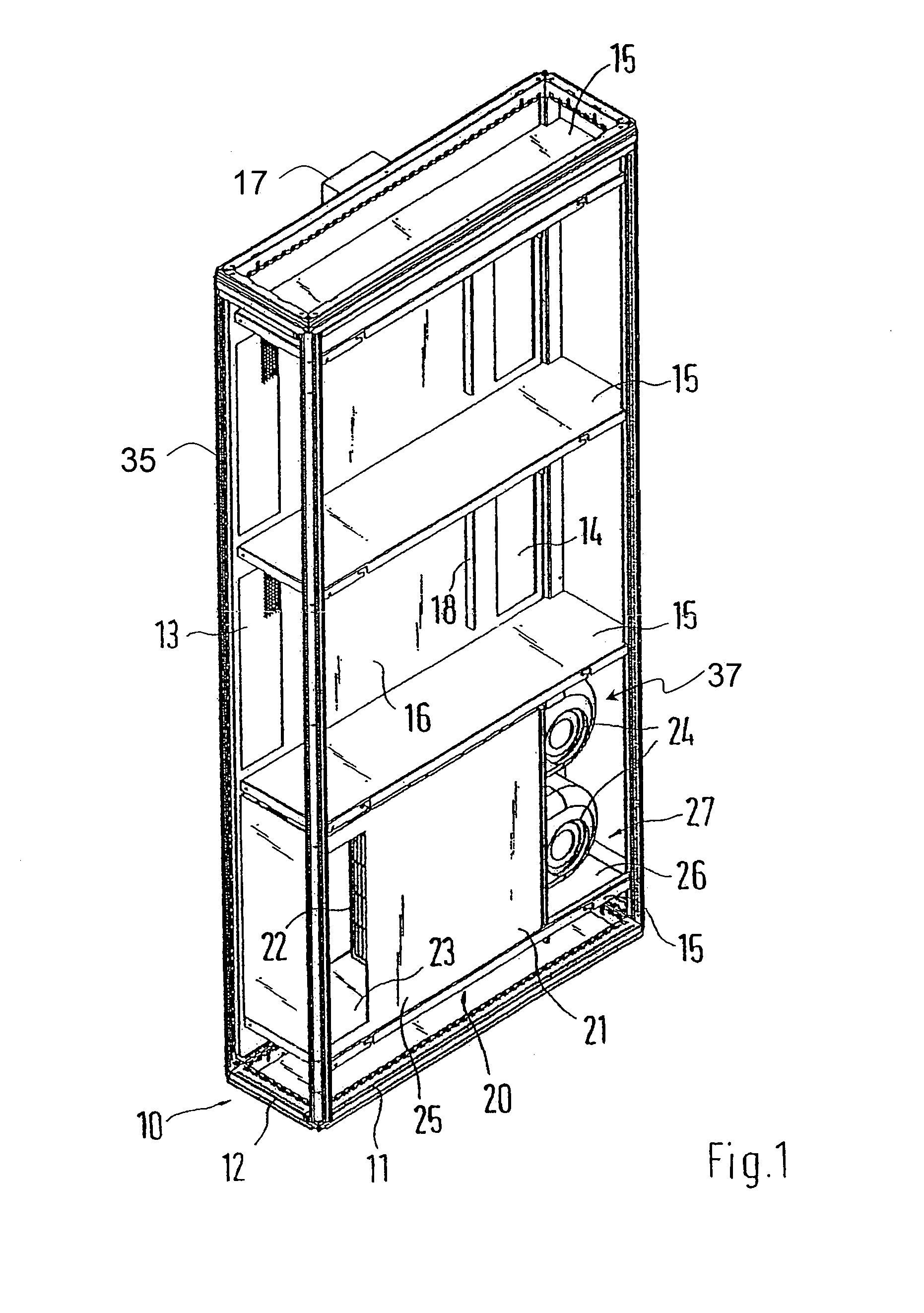
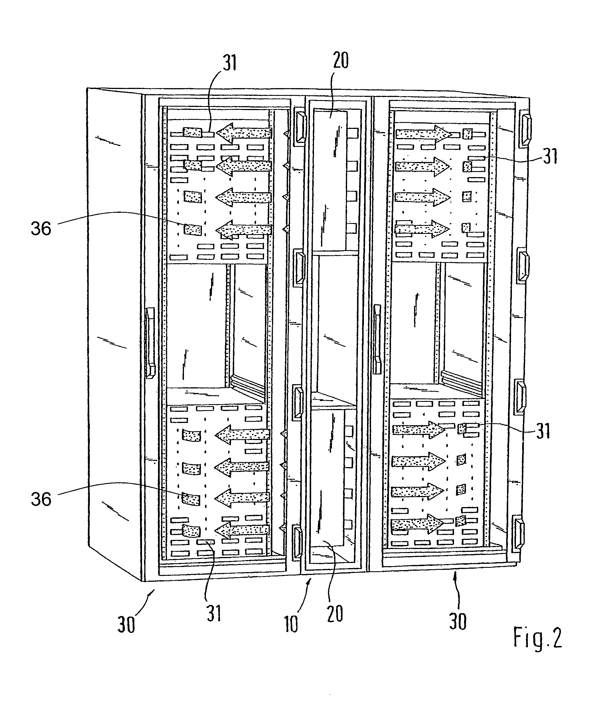
[0019]A cooling device 10 with a rack is represented in FIG. 1, and is put together from twelve profiled frame elements 11, 12, 35. The horizontal profiled frame elements 11, 12 form a bottom and cover frame, into whose corner areas the four vertical profiled frame elements 35 of identical cross section are welded. The receiving chamber formed by the rack is divided into three partial receiving chambers by horizontal compartment floors 15. The partial receiving chambers can be covered on both sides by lateral covers 16, and have cooling conduit structures 36. Each of the lateral covers 16 has an air inlet 14, a venting opening 13 and a sealing element 17. The narrow sides at the front and rear, as well as the roof, of the rack 15 are covered by suitable panels. The compartment floors 15 are fastened at the vertical profiled frame element 35 and each is used for receiving a cooling module 20. In this case, each cooling module is put together from two components, a heat exchanger unit...


PUM


Abstract

An assembly of devices including at least one switchgear cabinet and a cooling device. The switchgear cabinet has a closed interior, in which electric installations can be housed. The cooling device is attached in the vicinity of or near a lateral surface of the switchgear cabinet that runs vertically with respect to the front face, extending at least over part of the height of the switchgear cabinet and having a spatial connection with the interior via at least one air inlet and at least one vent outlet. The cooling device includes a receiving chamber that houses at least one heat exchanger. This invention facilitates the adaptation of the cooling device in superstructures of this type to modified cooling requirements. To achieve this, at least sections of the receiving chamber of the cooling device are divided into two or more receiving sub-chambers that are situated one above the other and a cooling module is housed in at least one of the receiving sub-chambers.

Description

BACKGROUND OF THE INVENTION[0001]1. Field of the Invention[0002]This invention relates to a device arrangement with at least one switchgear cabinet and one cooling device, wherein the switchgear cabinet has a closed interior in which electrical built-ins can be housed, the cooling device is installed in the area of a lateral surface of the switchgear cabinet which extends vertically with respect to the front and at least over a portion of the height of the switchgear cabinet, and is in spatial connection with the interior through at least one air inlet and at least one venting opening, and the cooling device has a receiving chamber in which at least one heat exchanger is housed.[0003]2. Discussion of Related Art[0004]A device arrangement is known from the company catalog of Rittal, Manual 30, page 448. In this case the cooling device has a closed housing, which can be installed on the switchgear cabinet in place of a door or a lateral wall. A heat exchanger is placed into the housin...

Claims


Application Information

Patent Timeline
Patent Type & Authority Patents(United States)
IPC IPC(8): H05K5/00H05K7/20F28D15/00G06F1/20H02B1/56
CPCH05K7/20754
Inventor NICOLAI, MICHAELDÖRRICH, MARTIN
Owner RITTALWERK RUDOLF LOH GMBH & CO KG
Why Eureka
Try Eureka