Electronic apparatus

a technology of electronic equipment and acoustic power supply, which is applied in the direction of electrical equipment casings/cabinets/drawers, instruments, applications, etc., can solve the problems of increasing the size of the server computer, no airflow to run into the space behind the wall member, etc., and achieve the effect of reducing the siz

Active Publication Date: 2008-01-15
FUJITSU LTD
View PDF11 Cites 17 Cited by
  • Summary
  • Abstract
  • Description
  • Claims
  • Application Information

AI Technical Summary

Benefits of technology

[0007]It is accordingly an object of the present invention to provide an electronic apparatus capable of a reduction in size without causing hindrance of airflow.
[0009]The second duct is allowed to define the air outlet opposed to a portion of the air inlet of the first duct in the electronic apparatus. The wall member closes the air inlet of the first duct at a position outside the air outlet of the second duct. An opening is formed in the wall member. The opening enables a connection between the outer space of the second duct and the air inlet of the first duct. Airflow enters the air inlet of the first duct from the air outlet of the second duct as well as from the opening of the wall member. The airflow is thus allowed to run into a space behind the wall member. The airflow of a sufficient quantity runs through the first duct from the air inlet of the first duct toward the air outlet of the first duct. Moreover, the first duct or first unit can be placed at a position closer to the second duct or second unit. This results in a reduced size of the enclosure containing the first and second units.
[0010]The first unit of the electronic apparatus may include a printed wiring board incorporated in the first duct, the printed wiring board extending from the air inlet of the first duct toward the air outlet of the first duct. The airflow of a sufficient quantity runs through the first duct from its air inlet toward its air outlet as described above. The airflow can run along the printed wiring board. The airflow can efficiently absorb heat from the printed wiring board. The second unit may include a printed wiring board incorporated within the second duct, the printed wiring board extending from the air inlet of the second duct toward the air outlet of the second duct. The airflow can efficiently absorb heat from the printed wiring board in the same manner as mentioned above. In this case, the electronic apparatus may further comprise a back panel placed in the enclosure, the back panel receiving the first and second units for connection. Additionally, the electronic apparatus may further comprise a fan having blades opposed to the air outlet of the first duct.
[0012]The second unit has a depth or third dimension larger than the depth or third dimension of the first unit in the electronic apparatus. The opening defined at the bottom of the second unit is thus partly opposed to the opening defined at the top of the first unit. The wall member closes the opening defined at the bottom of the second unit at a position outside the opening defined at the top of the first unit. The opening is formed in the wall member. Airflow enters the opening defined at the bottom of the second unit from the opening defined at the top of the first unit as well as from the opening of the wall member. The airflow is thus allowed to run into a space behind the wall member. The airflow of a sufficient quantity runs through the second unit from the bottom of the second unit toward the top of the second unit. Moreover, the second unit can be placed at a position closer to the first unit. This results in a reduced size of the enclosure containing the first and second units.

Problems solved by technology

However, no airflow is allowed to run into a space behind the wall member because the air inlets of the ducts of the system board units are designed to be larger than the air outlets of the ducts of the input / output units as described above.
This inevitably causes an increase in the size of the server computer.

Method used


Image

  • Electronic apparatus
  • Electronic apparatus
  • Electronic apparatus

Examples


Embodiment Construction

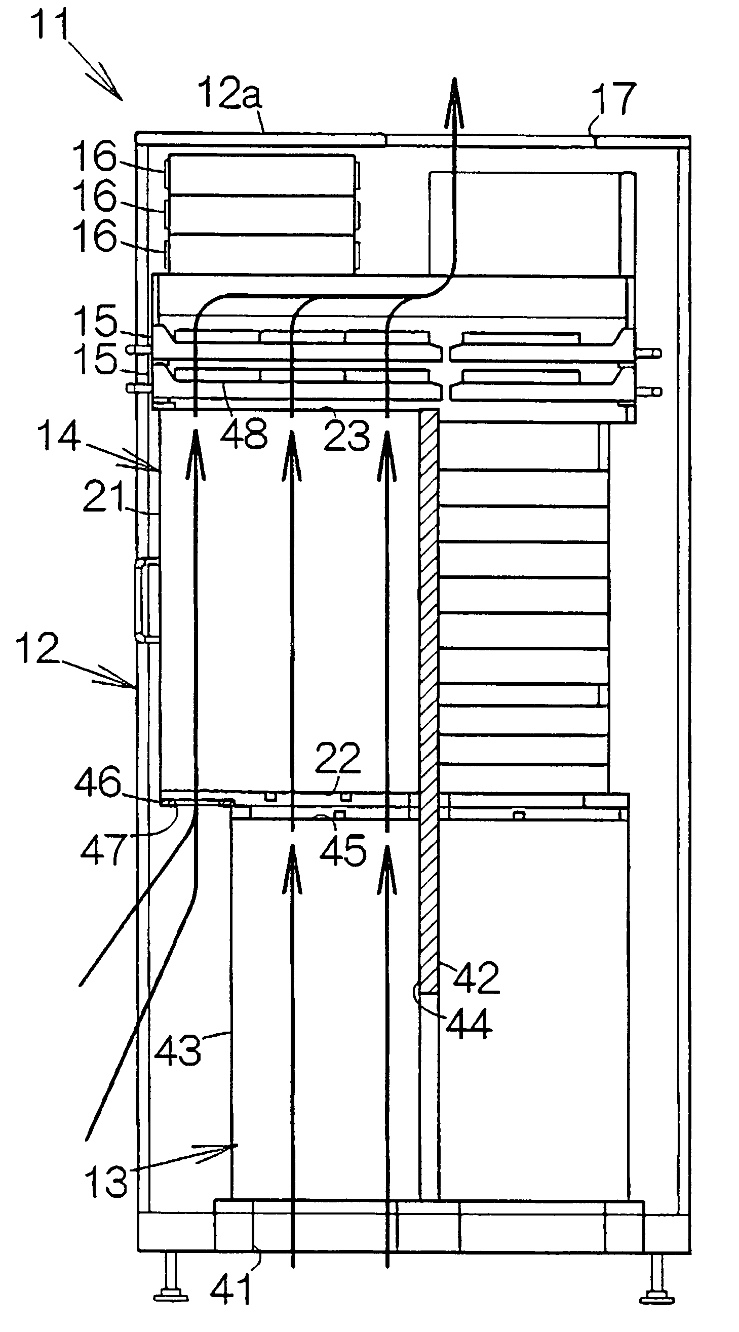
[0021]FIG. 1 schematically illustrates a server computer 11 as a specific example of an electronic apparatus according to the present invention. The server computer 11 includes an enclosure 12. Four input / output units 13 are mounted on the bottom rack of the enclosure 12, for example. The input / output units 13 are arranged in parallel with one another. The input / output units 13 are individually coupled to a back panel placed within the enclosure 12 as described later in detail.

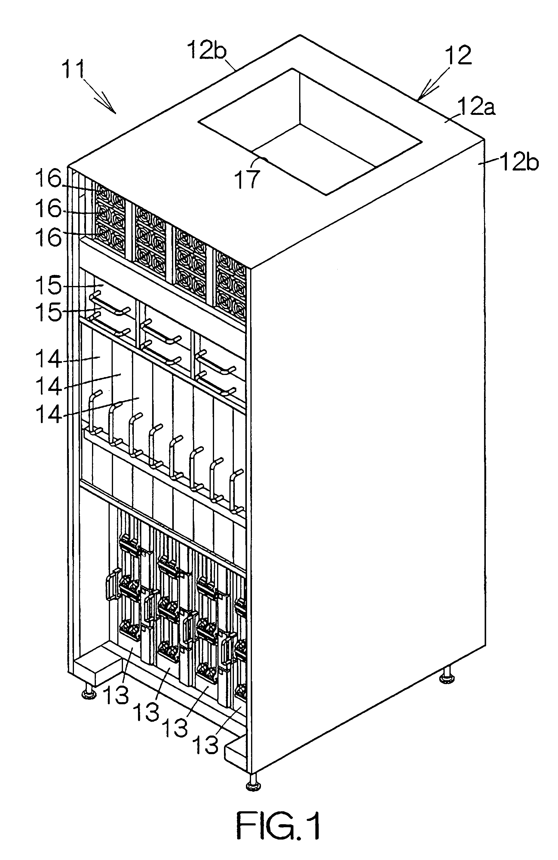
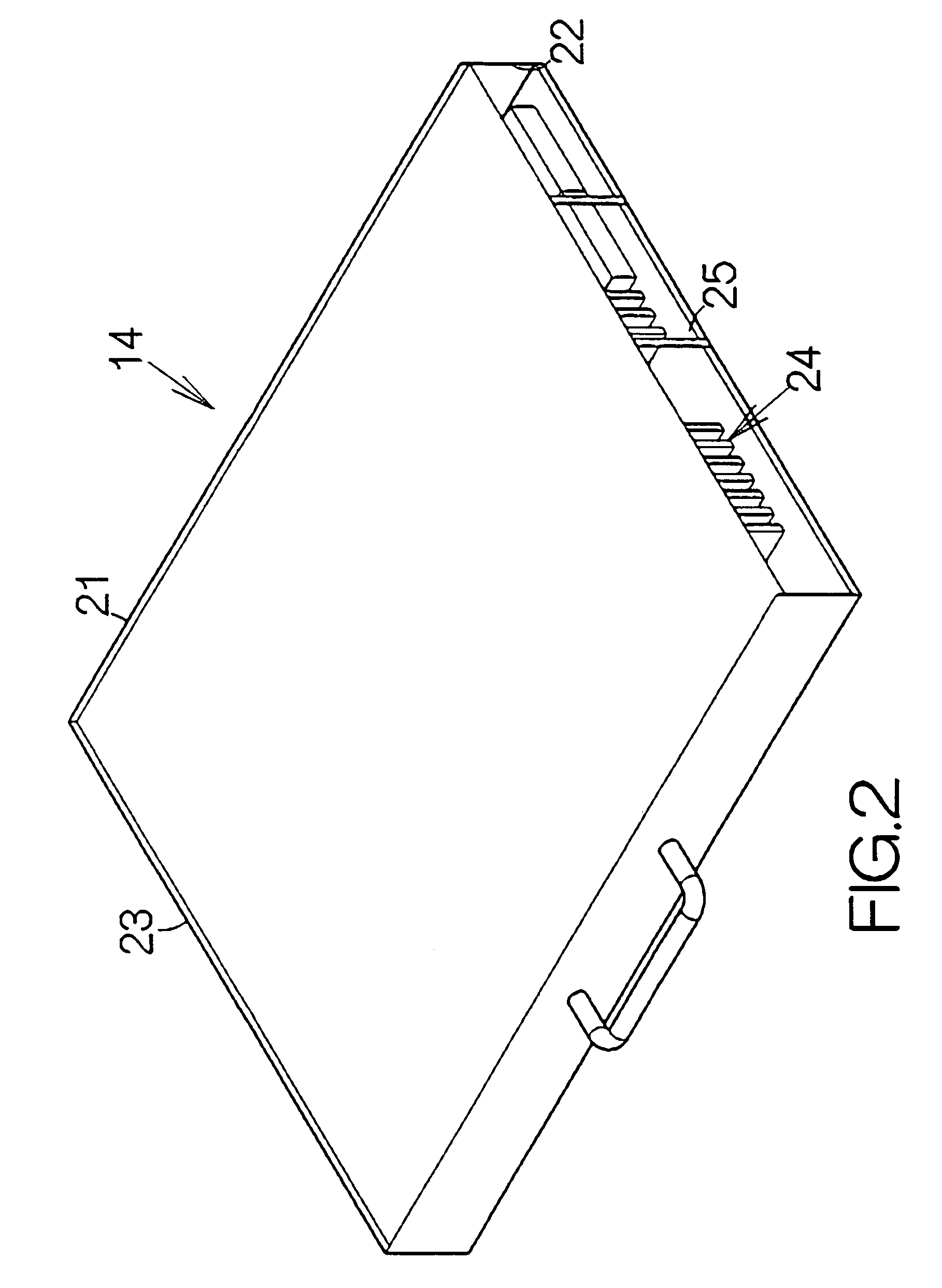
[0022]Eight system board units 14 are mounted on the middle rack of the enclosure 12, for example. The system board units 14 are arranged in parallel with one another. The system board units 14 are individually coupled to the back panel in the same manner as the input / output units 13. The system board units 14 have dimensions larger than that of the input / output units 13.

[0023]Fan units 15 are mounted on the upper rack of the enclosure 12. The individual fan unit 15 includes axial flow fans, for example. Rotor...


PUM


Abstract

A second duct is designed to oppose its air outlet to a portion of an air inlet of a first duct in an electronic apparatus. The wall member closes the air inlet of the first duct at a position outside the air outlet of the second duct. An opening is defined in the wall member. The opening enables a connection between the outer space of the second duct and the air inlet of the first duct. Airflow enters the air inlet of the first duct from the air outlet of the second duct as well as from the opening of the wall member, respectively.

Description

BACKGROUND OF THE INVENTION[0001]1. Field of the Invention[0002]The present invention relates to an electronic apparatus such as a server computer.[0003]2. Description of the Prior Art[0004]System board units and input / output units are incorporated in a server computer. The system board units and the input / output units include printed circuit board units. The printed circuit board units are kept in an upright attitude. The printed circuit board units are respectively incorporated in ducts extending in the vertical direction.[0005]The input / output units are designed to be smaller than the system board units in size. The air outlets of the ducts of the input / output units are thus opposed to portions of the air inlets of the ducts of the system board units. A predetermined wall member is utilized to close the air inlets of the ducts of the system board units at a position outside the air outlets of the ducts of the input / output units.[0006]A fan or fans are opposed to the air outlets o...

Claims


Application Information

Patent Timeline
Patent Type & Authority Patents(United States)
IPC IPC(8): H05K7/20
CPCH05K7/20736
Inventor FUJIYA, HIROMITSUMAKABE, EIJI
Owner FUJITSU LTD
Why Eureka
Try Eureka