Load controller for hydrostatic transmission in work vehicles

a technology for hydrostatic transmission and load controller, which is applied in the direction of fluid couplings, gearings, couplings, etc., can solve the problems that the large electric motor used in the conventional load controller becomes unnecessary, and achieve the effect of simplifying and minimizing the structur

Inactive Publication Date: 2008-01-22
KANZAKI KOKYUKOKI MFG
View PDF14 Cites 14 Cited by
  • Summary
  • Abstract
  • Description
  • Claims
  • Application Information

AI Technical Summary

Benefits of technology

[0011]The present invention provides a load controller for use in a hydrostatic transmission for a work vehicle that is free from control failure caused by deterioration of the constituent components, and that can be miniaturized and simplified in structure compared to conventional load controllers.
[0013]In the present invention, an oil line that has high pressure during forward movement in an oil-hydraulic closed circuit of the hydrostatic transmission (HST) is connected to an oil line that has low pressure during forward movement or an oil tank via an opening / closing valve so as to route the high-pressure working oil to a low-pressure oil line or an oil tank when an overload is applied to the engine. Therefore, it is possible to eliminate the overload by reducing the power distribution ratio to the traveling system, and increasing the power distribution ratio to an implement. As a result, a large electric motor as used in a conventional load controller becomes unnecessary, and the load can be controlled by using a small opening / closing valve. Furthermore, because no cushioning elastic body is used, the occurrence of control failure caused by deterioration of constituent components with time is also reduced.

Problems solved by technology

As a result, a large electric motor as used in a conventional load controller becomes unnecessary, and the load can be controlled by using a small opening / closing valve.

Method used


Image

  • Load controller for hydrostatic transmission in work vehicles
  • Load controller for hydrostatic transmission in work vehicles
  • Load controller for hydrostatic transmission in work vehicles

Examples


first embodiment

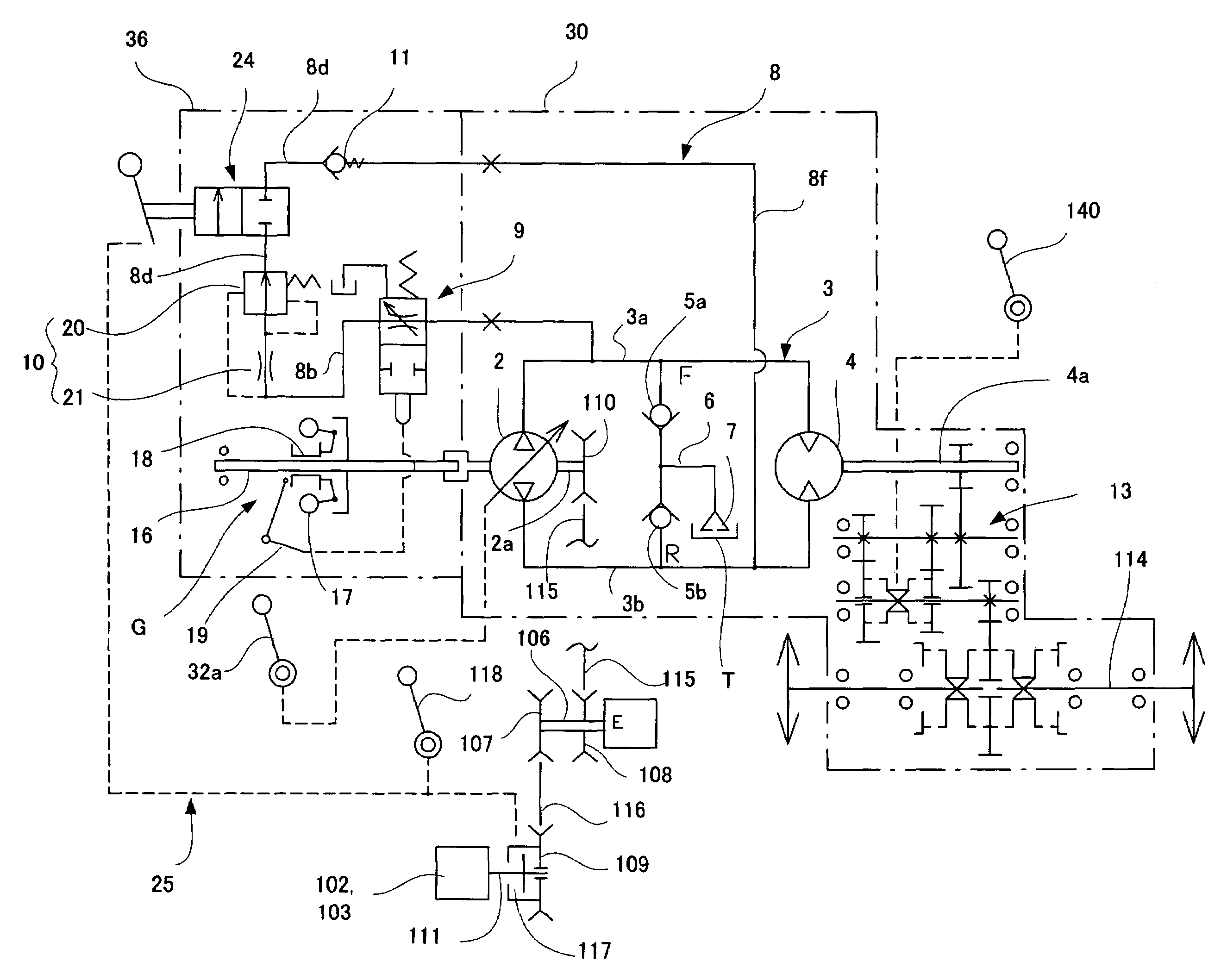
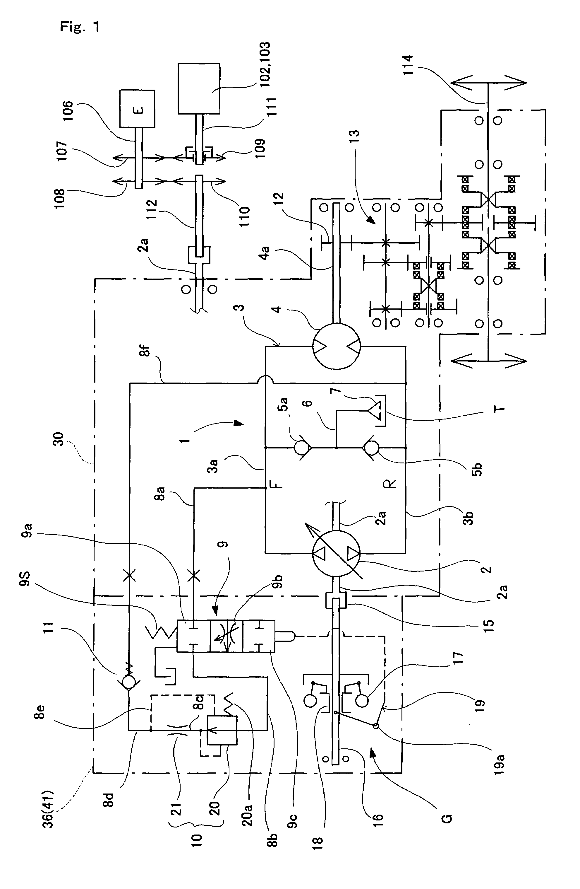
[0039]a load controller of the present invention is explained below. FIG. 1 shows an oil-hydraulic circuit of a hydrostatic transmission provided with a load controller. The hydrostatic transmission 1 comprises an oil-hydraulic pump 2 driven by an engine E, and an oil-hydraulic motor 4 (actuator) that is connected to the oil-hydraulic pump 2 via oil lines 3a and 3b that form an oil-hydraulic closed circuit 3.

[0040]In the example shown in the figure, the oil-hydraulic pump 2 is a variable-displacement oil-hydraulic pump, and the oil-hydraulic motor 4 is a fixed displacement motor. The oil line 3a has high pressure during forward movement, and the oil line 3b has low pressure during forward movement. The oil lines 3a and 3b meet at an oil supplement circuit 6 via check valves 5a and 5b. When either the oil line 3a or oil line 3b has negative pressure, oil can be supplied to the oil supplement circuit 6 from the oil tank T via a filter 7. This is an example of a self-priming pump; howe...

fifth embodiment

[0077]the load controller for a hydrostatic transmission mounted on a work vehicle of the present invention is explained below with reference to FIGS. 9 to 12.

[0078]The load controller for a hydrostatic transmission mounted on a work vehicle of the fifth embodiment uses a torque sensing governor as an opening / closing valve controller. FIG. 9 is a side elevational view showing the entire structure of the snowplow. FIG. 10 is a partially enlarged cross-sectional view of the opening / closing valve controller. FIG. 11 is a cross-sectional view illustrating the hydrostatic transmission, and FIG. 12 is an oil-hydraulic circuit diagram.

[0079]As shown in FIG. 9, the snowplow functions as a work vehicle comprising a controller 100, an engine chamber 101, an auger 102, blower 103, a duct 104, and a crawler 105. Output from an output shaft 106 is branched into a PTO shaft 111 (implement system) for driving the auger 102 via pulleys 108 to 110 and a traveling system driven by a crawler 105 via a...

sixth embodiment

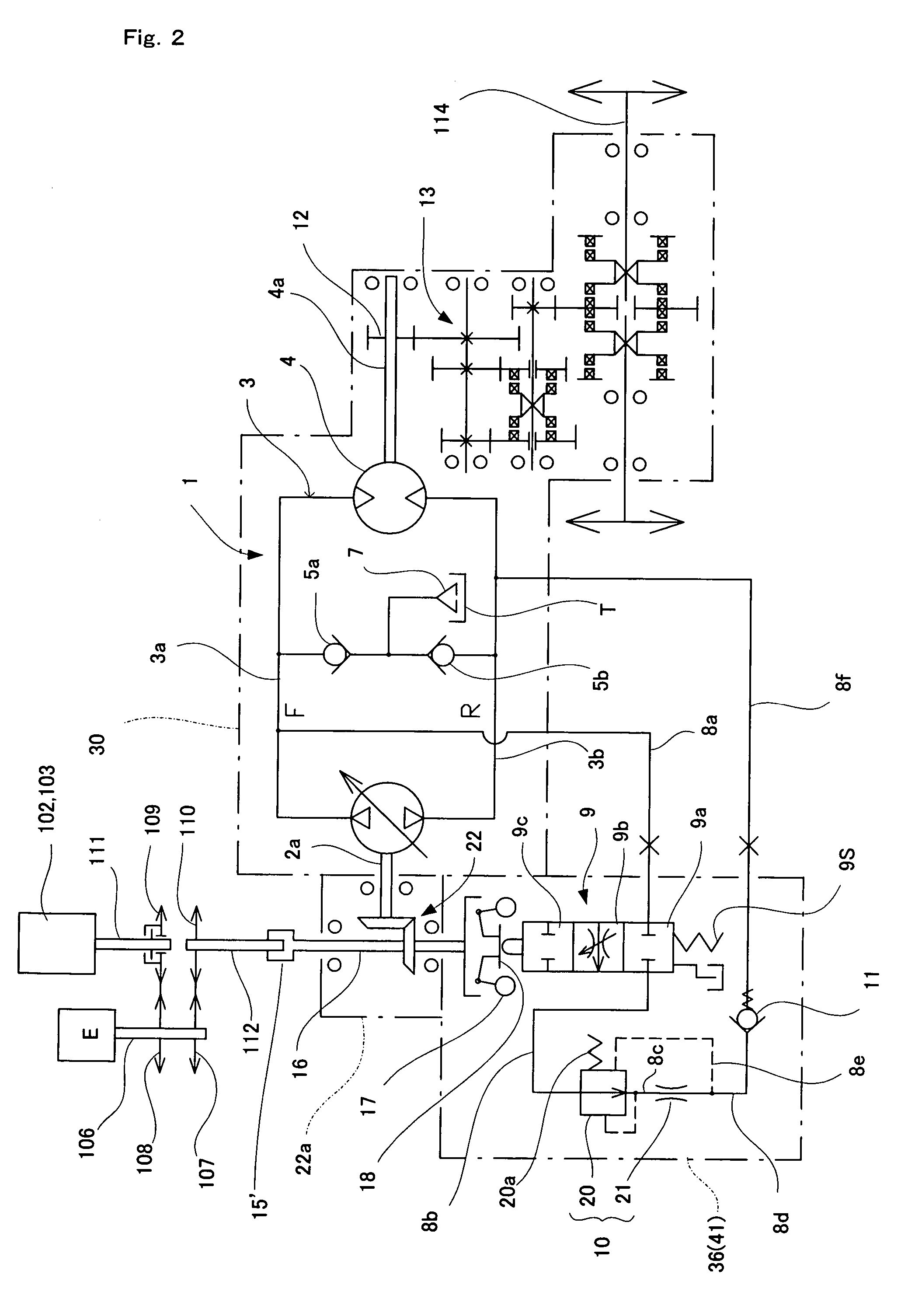
[0088]FIG. 13 is a diagram showing an oil-hydraulic circuit of a hydrostatic transmission provided with a load controller of the present invention. The hydrostatic transmission 1 comprises an oil-hydraulic pump 2 driven by an engine E, and an oil-hydraulic motor 4 (actuator) connected to an oil-hydraulic pump 2 via oil lines 3a and 3b which form an oil-hydraulic closed circuit 3. Note that an oil tank, a charge pump supplying oil from the oil tank, etc., are not shown in FIG. 13.

[0089]In this figure, the oil-hydraulic pump 2 is a variable-displacement oil-hydraulic pump, and the oil-hydraulic motor 4 is a fixed displacement motor. The oil line 3a has high pressure during forward movement, and the oil line 3b has low pressure during forward movement. The oil lines 3a and 3b meet at an oil supplement circuit 6 via check valves 5a and 5b. When either the oil line 3a or oil line 3b has negative pressure, oil can be supplied to the oil supplement circuit 6 from the oil tank T via a filte...


PUM


Abstract

Disclosed is a load controller for use in a hydrostatic transmission for a work vehicle. Power supplied from an engine is branched to drive an implement system and a traveling system. The hydrostatic transmission connects, in an oil-hydraulic closed circuit, an oil-hydraulic pump driven by the engine and an oil-hydraulic motor driven by the oil-hydraulic pump. The load controller includes a bypass oil line for bypassing an oil line that has high pressure during forward movement in the oil-hydraulic closed circuit to reach an oil line that has low pressure during forward movement or an oil tank; a first opening / closing valve for opening or closing the bypass oil line; and an opening / closing valve controller that detects a load applied to the engine while traveling during working and opens the first opening / closing valve when the load exceeds a predetermined level.

Description

TECHNICAL FIELD[0001]The present invention relates to a load controller for a hydrostatic transmission (HST) mounted on a work vehicle, such as a snowplow, a farm tractor, etc.BACKGROUND ART[0002]Usually, a snowplow, a farm tractor or like work vehicle is structured so that an auger or the like is driven using power that is branched and output from an engine or a power transmission system.[0003]For example, a snowplow comprises, as shown in FIG. 8, a controller 100, an engine chamber 101, an auger 102, a blower 103, a duct 104, and a crawler 105. Output from an output shaft 106 is branched into a PTO shaft 111 (implement system) for driving the auger 102 and a drive shaft 112 (traveling system) of the crawler 105 via pulleys 107 to 110. Rotational driving force is transmitted from the drive shaft 112 to an axle 114 via a transmission 113. A hydrostatic transmission is often used in such a work vehicle as a speed change gear.[0004]However, if an auger or like implement system becomes...

Claims


Application Information

Patent Timeline
Patent Type & Authority Patents(United States)
IPC IPC(8): F16D31/02F16H47/02F16H59/14F16H59/42F16H61/40F16H61/4035F16H61/4052F16H61/46F16H61/465
CPCF16H61/40F16H61/4035F16H61/4052F16H61/465F16H47/02F16H59/14F16H59/42
Inventor YASUDA, TOSHIFUMISAKIKAWA, SHIGENORIOHTSUKI, KAZUHIKO
Owner KANZAKI KOKYUKOKI MFG
Why Eureka
Try Eureka