
Method and device for producing pretensioned anchorings

a pretensioned anchoring and pretensioning technology, which is applied in the direction of caissons, bulkheads/piles, cutting machines, etc., can solve the problems of inability to introduce the anchoring device, the anchoring device having a great length may entail problems, and the time-consuming and labor-intensive problems of increasing the length of the anchoring devi

Inactive Publication Date: 2008-01-22
ALWAG TUNNELAUSBAU GMBH
View PDF26 Cites 5 Cited by
  • Summary
  • Abstract
  • Description
  • Claims
  • Application Information

AI Technical Summary

Benefits of technology

This approach simplifies the process by allowing immediate stabilization and compaction of soil or rock material, providing a reliable anchoring effect and reducing time expenditure, even in long boreholes, by securely filling the space between the jacket tube and the borehole wall with a curable fluid, enhancing the anchoring performance.

Problems solved by technology

That known prior art, in particular, involves the drawback that the borehole must be produced in a first method step, whereupon, after the removal of the drilling tool together with the drill rod assembly, the anchoring device is introduced into the optionally very long borehole in a further method step.
It is immediately apparent that the two separate operating steps not only require accordingly more time, but that optionally the subsequent introduction of such an anchoring device having a great length may entail problems.
Furthermore, it is to be anticipated that the removal of the drilling device together with the drill rod assembly and the subsequent introduction of an anchoring device is feasible only in comparatively solid soil or rock, where it must be safeguarded that no material will break into the borehole, for instance, during the drilling procedure or after the removal of the drilling tool and prior to the final introduction of the anchoring device, which would block the borehole and, hence, render the introduction of the anchoring device impossible.
By means of such packers, it is, however, impossible to provide a reliable anchoring effect intended to stabilize the surrounding soil or rock material, particularly where a plurality of anchors to be adjacently arranged are provided, so that additional anchoring means such as, for instance, the application of a curing material will optionally have to be provided.

Method used


Image

  • Method and device for producing pretensioned anchorings
  • Method and device for producing pretensioned anchorings
  • Method and device for producing pretensioned anchorings

Examples


Embodiment Construction

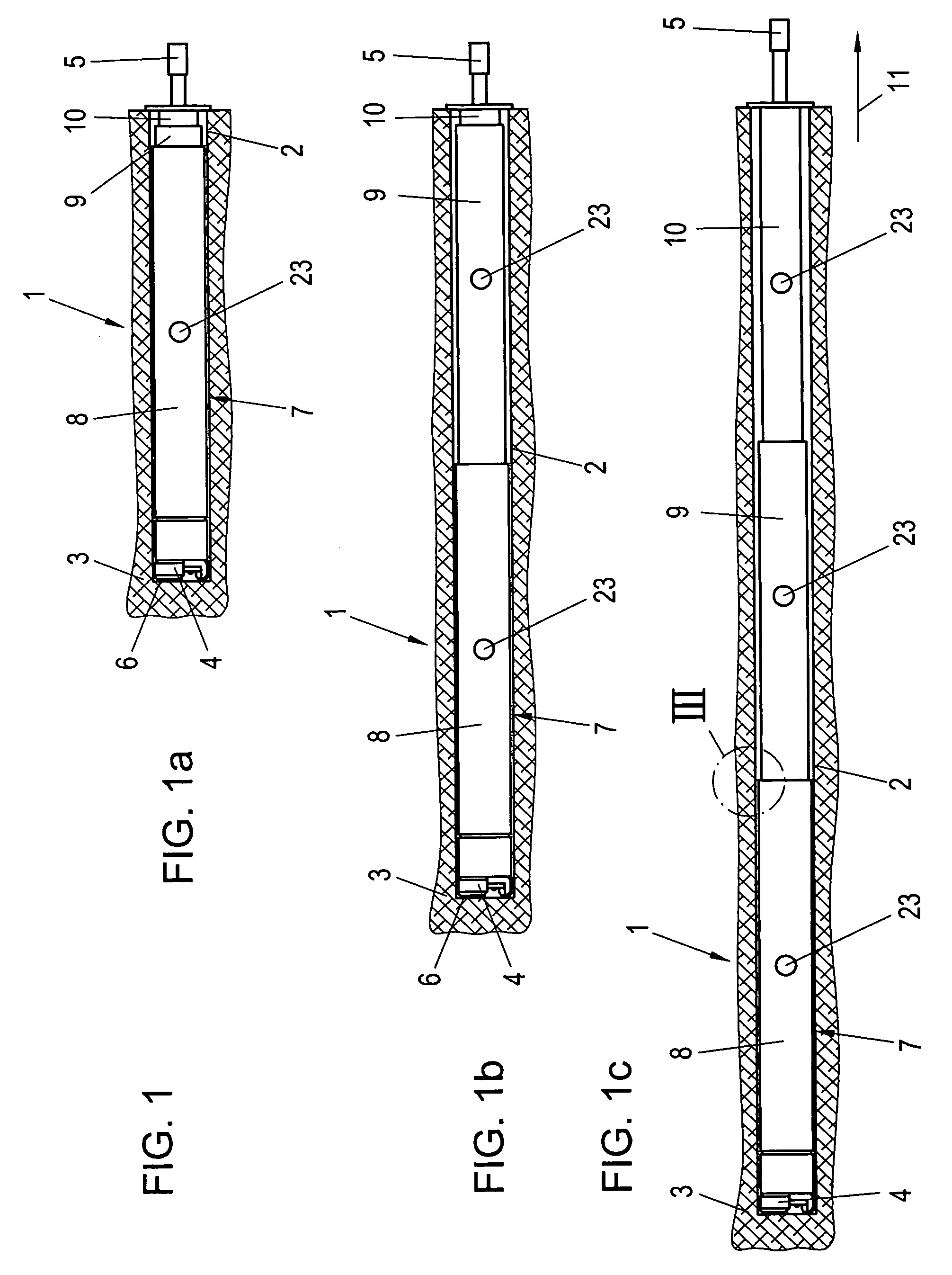
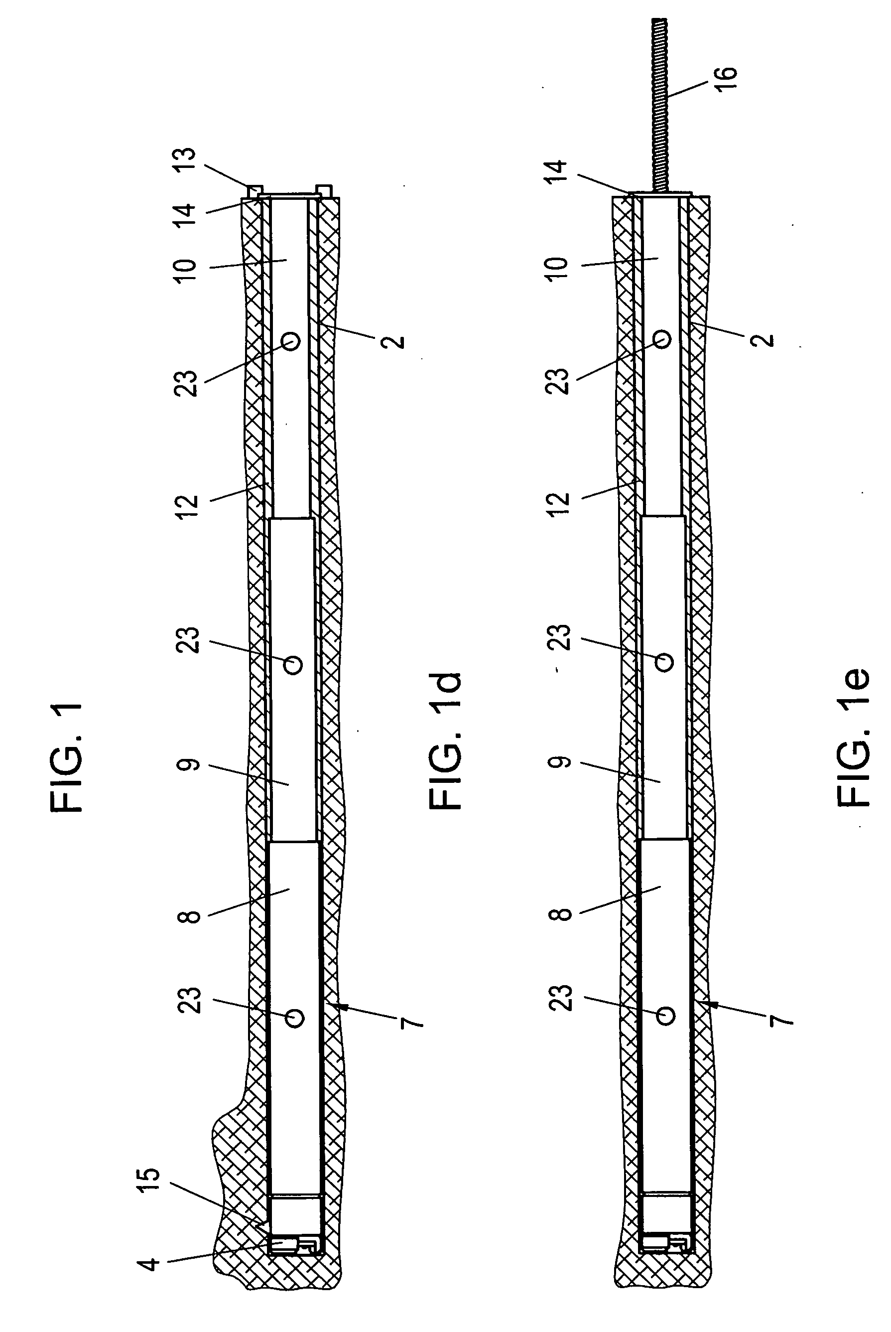
[0039]FIG. 1 depicts different steps in the production of a borehole using a device, which is generally denoted by 1, for the drilling, in particular percussion drilling or rotary percussion drilling, of a hole 2 in soil or rock material schematically indicated by 3.

[0040]In the illustration according to FIG. 1, a schematically indicated drill bit 4 is each provided, which is set into a percussive and / or rotary percussive movement by a drive not illustrated in detail via a drill rod assembly, which is denoted by 5 in FIGS. 1a to 1c , in order to form the borehole 2, excavation elements 6 being indicated on the drill bit 4.

[0041]A jacket tube, which is generally denoted by 7, follows upon the end of the drill bit 4 facing away from the interior of the borehole, wherein it is apparent that the jacket tube 7 is comprised of a plurality of jacket tube elements telescopically arranged one within the other and denoted in the Figures by 8, 9 and 10, respectively.

[0042]As a function of the ...


PUM


Abstract

A method and device for boring, particularly percussion boring or rotary percussion boring, a hole in soil or rock material and for forming an anchoring. A borehole is formed by inserting a drill bit, and a casing tube is placed inside the borehole during the boring process. Once the borehole is completed, the boring rods are detached from the drill bit and removed from the borehole. The periphery of the casing tube is provided with a number of passage openings for discharging hardenable material. A tensioning device for the anchor, particularly an anchor plate and a screw that can be screwed onto the casing tube, can be fixed to the end of the casing tube protruding from the borehole. Anchoring or fixing elements for anchoring the casing tube on the surrounding inner wall of the borehole are provided, in particular, on the end area of the casing tube oriented toward the drill bit.

Description

[0001]This is a continuation of PCT / AT05 / 000101 filed Mar. 22, 2005 and published in German.FIELD OF THE INVENTION[0002]The present invention relates to a method for drilling, in particular percussion drilling or rotary percussion drilling, a hole in soil or rock material and for forming an anchoring in said hole, wherein a borehole is formed by the introduction of a drill bit mounted on a drill rod assembly and a jacket tube is introduced into the borehole during the drilling procedure, wherein the drill rod assembly is separated from the drill bit and removed from the borehole upon completion of the borehole. The invention further relates to a device for drilling, in particular percussion drilling or rotary percussion drilling, a hole in soil or rock material and for forming an anchoring, wherein a borehole is formed by the introduction of a drill bit and a jacket tube is introduced into the borehole during the drilling procedure, wherein the drill rod assembly is separated from t...

Claims


Application Information

Patent Timeline
Patent Type & Authority Patents(United States)
IPC IPC(8): E21B7/20E02D23/08E02D5/74E02D5/76E21D21/00
CPCE21D21/0033E21D21/008E21D2021/0053E21D21/0053E21D21/00
Inventor MOCIVNIK, JOSEFEGGER-MOCIVNIK, RENEWAGNER, ALFREDBOHM, KARL
Owner ALWAG TUNNELAUSBAU GMBH
Learn More