Top cowl for outboard motor and mold for forming top cowl

a top cowl and motor technology, applied in the direction of marine propulsion, propulsive elements, vessel construction, etc., can solve the problems of requiring additional manufacturing procedures, heavy top cowls, and inability to recycle, so as to improve the overall appearance enhance the mechanical properties of the top cowl, and reduce the effect of sprue and/or overflow marks

Inactive Publication Date: 2008-01-22
YAMAHA MARINE KK
View PDF7 Cites 2 Cited by
  • Summary
  • Abstract
  • Description
  • Claims
  • Application Information

AI Technical Summary

Benefits of technology

[0009]An aspect of the present invention disclosed herein includes the realization that a top cowl for an outboard motor can be rigid and lightweight cowling while having a desirable appearance. The top cowl can have one or more reinforcement ribs that enhance the mechanical properties of the top cowl. These ribs can also aid in the casting process so as to reduce marks from a sprue and / or overflow, thus improving the overall appearance of the top cowl.
[0011]In some aspects, an outboard motor has a top cowl and a bottom cowl. A rib protrudes inwardly from an inner surface of a top cowl into an engine compartment. A bottom opening edge of the top cowl mates with the bottom cowl. The rib extends along the length of top cowl from the forward end of the opening edge to a rearward end of the opening edge. A mold for forming the top cowl has an entrance sprue that is located in a position corresponding to the position of one end of an opening edge of the top cowl. An exit sprue of the mold is located in a position corresponding to the position of an opposing end of the opening edge of the top cowl. A top cavity of the mold allows part of molten metal to flow from the entrance sprue to the exit sprue through a top cavity. Side cavities allow the remaining molten metal to flow from the entrance sprue to the exit sprue through the side cavities, in which the part of molten metal that flows through the top cavity faster than the flows of the remaining molten metal passing through the side cavities.

Problems solved by technology

Unfortunately, these top cowls are heavy and non-recyclable.
Unfortunately, these top cowls need to have a relatively large minimum thickness to ensure the top cowl is sufficiently rigid to protect the engine.
This minimum thickness can result in a relatively heavy top cowl.
Unfortunately, marks from a sprue or overflow that remains on the exposed surface of a casting article may require additional manufacturing procedures to produce an article having a suitable appearance.
This significantly limits the layout of the sprue and overflow to particular locations, thus limiting design flexibility.
These design constraints can also lead to excessively thick portions of the cowl that undesirably increase the overall weight of the cowl.

Method used


Image

  • Top cowl for outboard motor and mold for forming top cowl
  • Top cowl for outboard motor and mold for forming top cowl
  • Top cowl for outboard motor and mold for forming top cowl

Examples


Embodiment Construction

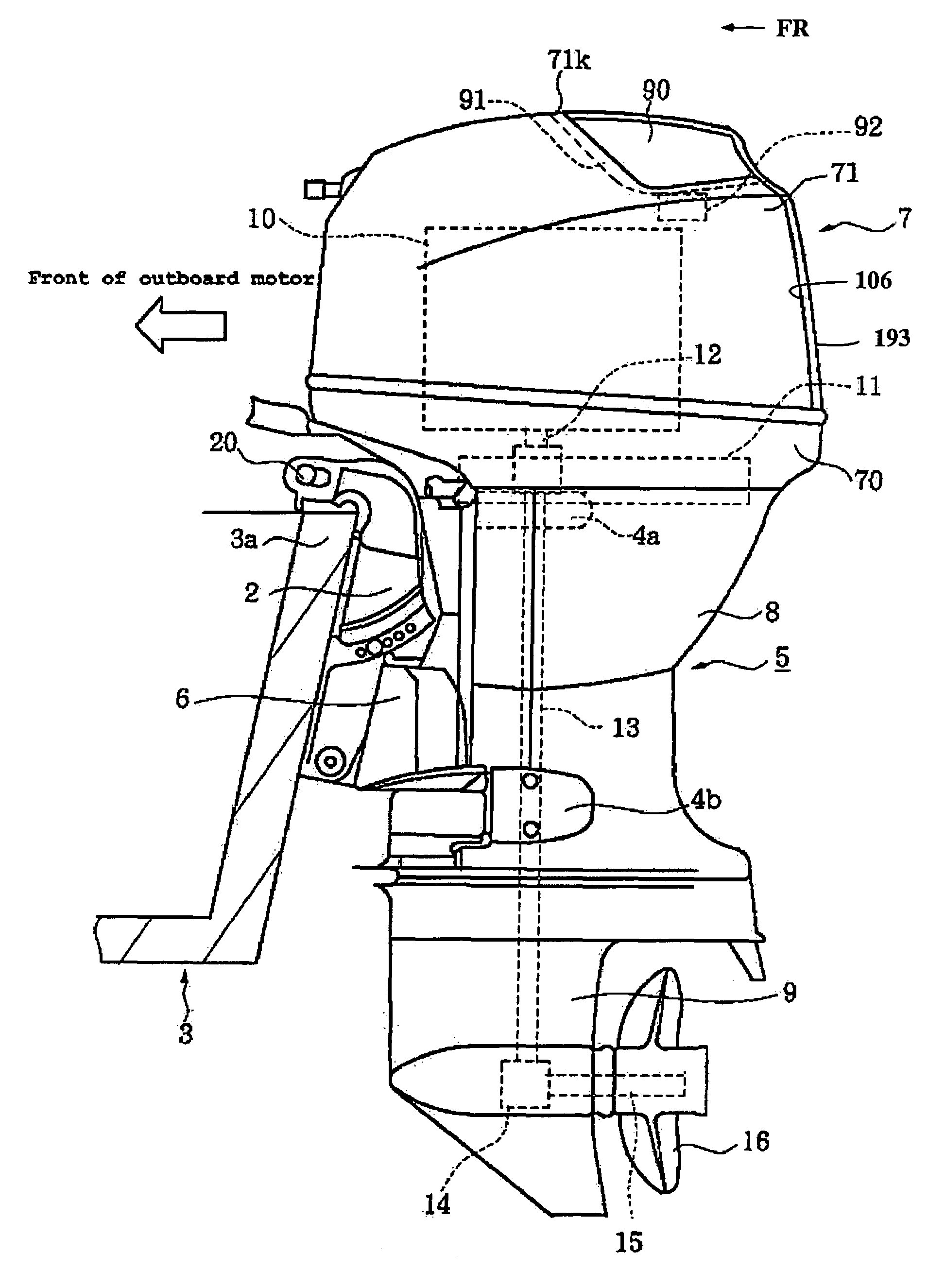
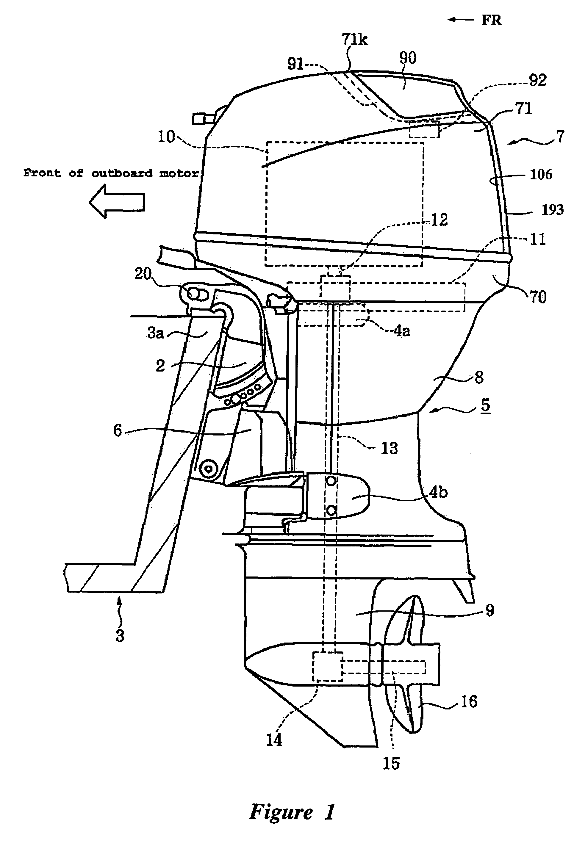
[0024]With reference to FIG. 1, a watercraft has an outboard motor 1 that is configured in accordance with certain features, aspects, and advantages of the present invention. The outboard motor 1 is a typical marine drive, and thus all the embodiments below are described in the context of an outboard motor. The embodiments, however, can be applied to other marine drives, as will become apparent to those of ordinary skill in the art. The arrow FR in the drawing indicates the forward direction in which the watercraft travels. It will be appreciated, however, that the illustrated embodiments can be located or oriented in a variety of desired positions.

[0025]The illustrated watercraft of FIG. 1 has a hull 3 that can float in the water. The hull 3 carries the outboard motor 1, which has a propulsion unit 5 and an internal combustion engine 10 (shown in phantom). The engine 10 of the outboard motor 1 powers the propulsion unit 5 which propels the watercraft. The illustrated propulsion uni...


PUM

PropertyMeasurementUnit
widthaaaaaaaaaa
timeaaaaaaaaaa
lengthaaaaaaaaaa

Abstract

An outboard motor has a top cowl and a bottom cowl. A elongate thickened portion protrudes inwardly from an inner surface of the top cowl into an engine compartment. A bottom opening edge of the top cowl mates with the bottom cowl. The elongate thickened portion extends along the length of top cowl from the forward end of the opening edge to a rearward end of the opening edge. A mold for forming the top cowl has an entrance sprue that is located in a position corresponding to the position of one end of an opening edge of the top cowl. An exit sprue of the mold is located in a position corresponding to the position of an opposing end of the opening edge of the top cowl. The mold defines a top cavity and side cavities that are used to mold the top cowl.

Description

PRIORITY INFORMATION[0001]The present application is based on and claims priority under 35 U.S.C. § 119(a-d) to Japanese Patent Application No. 2004-378525, filed on Dec. 28, 2004, the entire contents of which is expressly incorporated by reference herein.BACKGROUND OF THE INVENTION[0002]1. Field of the Invention[0003]The present invention generally relates to top cowls for outboard motors and more particularly relates to top cowls that cover engines of outboard motors and molds for forming such top cowls.[0004]2. Description of the Related Art[0005]Outboard motors can be used to propel watercraft. Outboard motors often have an engine disposed within a protective cowling. The protective cowling typically includes a top cowl and a bottom cowl. Air flows through the cowling to the engine. Air inlet openings at the rear of the cowling can provide fluid communication between the engine and ambient air outside of the cowling. The air inlet openings are typically positioned rearwardly bec...

Claims


Application Information

Patent Timeline
Patent Type & Authority Patents(United States)
IPC IPC(8): B63H20/32
CPCB22D17/22B63H20/32
Inventor NAKAMURA, DAISUKE
Owner YAMAHA MARINE KK
Why Eureka
Try Eureka