Electric driving tool with driver propelled by flywheel inertia

a technology of electric driving tools and flywheels, which is applied in the direction of manufacturing tools, percussive tools, portable drilling machines, etc., can solve the problems of not providing the user with the desired degree of flexibility and freedom, large size and/or weight, and relatively cumbersome work

Inactive Publication Date: 2008-01-29
BLACK & DECKER INC
View PDF181 Cites 30 Cited by
  • Summary
  • Abstract
  • Description
  • Claims
  • Application Information

AI Technical Summary

Benefits of technology

[0007]In another form, the present teachings provide a tool with a driver, which is translatable along a driver axis, and a motor assembly having an electric motor, a flywheel, a roller and an actuator. The electric motor is selectively operable for driving the flywheel. The actuator is selectively operable for translating the roller such that the roller drives the driver against the flywheel to permit energy to be transmitted from the flywheel to the driver. The electric motor is selected to substantially minimize energy losses associated with bringing a mechanical inertial of the motor assembly to a predetermined rotational speed while substantially minimizing an amount of time that is needed to bring the mechanical inertia to the predetermined rotational speed.

Problems solved by technology

Often times, however, the fastening tools that are available may not provide the user with a desired degree of flexibility and freedom due to the presence of hoses and such that couple the fastening tool to a source of pneumatic power.
Some of these nailers, however, are relatively large in size and / or weight, which renders them relatively cumbersome to work with.
Others require relatively expensive fuel cartridges that are not re-fillable by the user so that when the supply of fuel cartridges has been exhausted, the user must leave the work site to purchase additional fuel cartridges.
Yet other cordless nailers are relatively complex in their design and operation so that they are relatively expensive to manufacture and do not operate in a robust manner that reliably sets fasteners into a workpiece in a consistent manner.

Method used


Image

  • Electric driving tool with driver propelled by flywheel inertia
  • Electric driving tool with driver propelled by flywheel inertia
  • Electric driving tool with driver propelled by flywheel inertia

Examples


Embodiment Construction

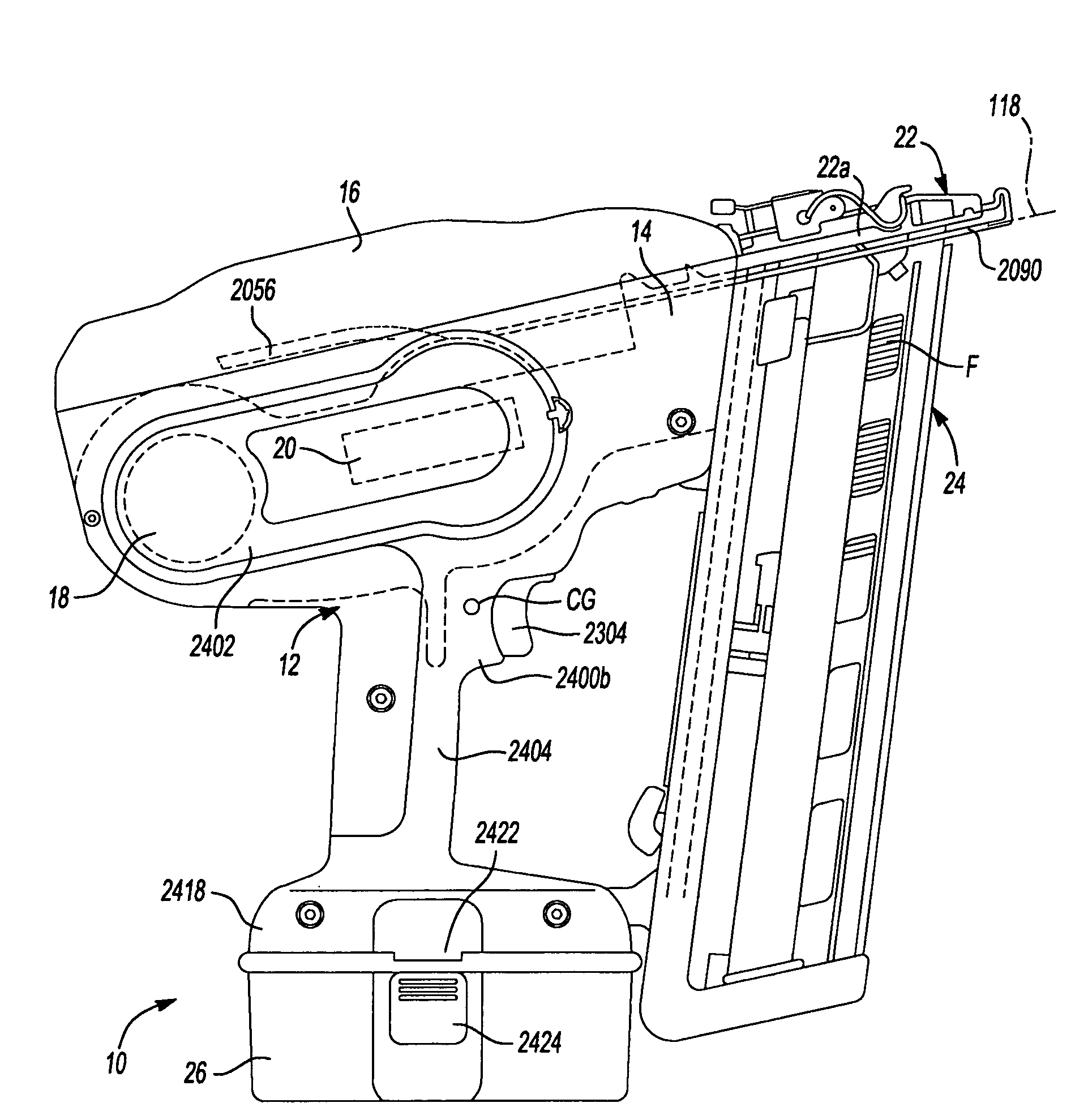
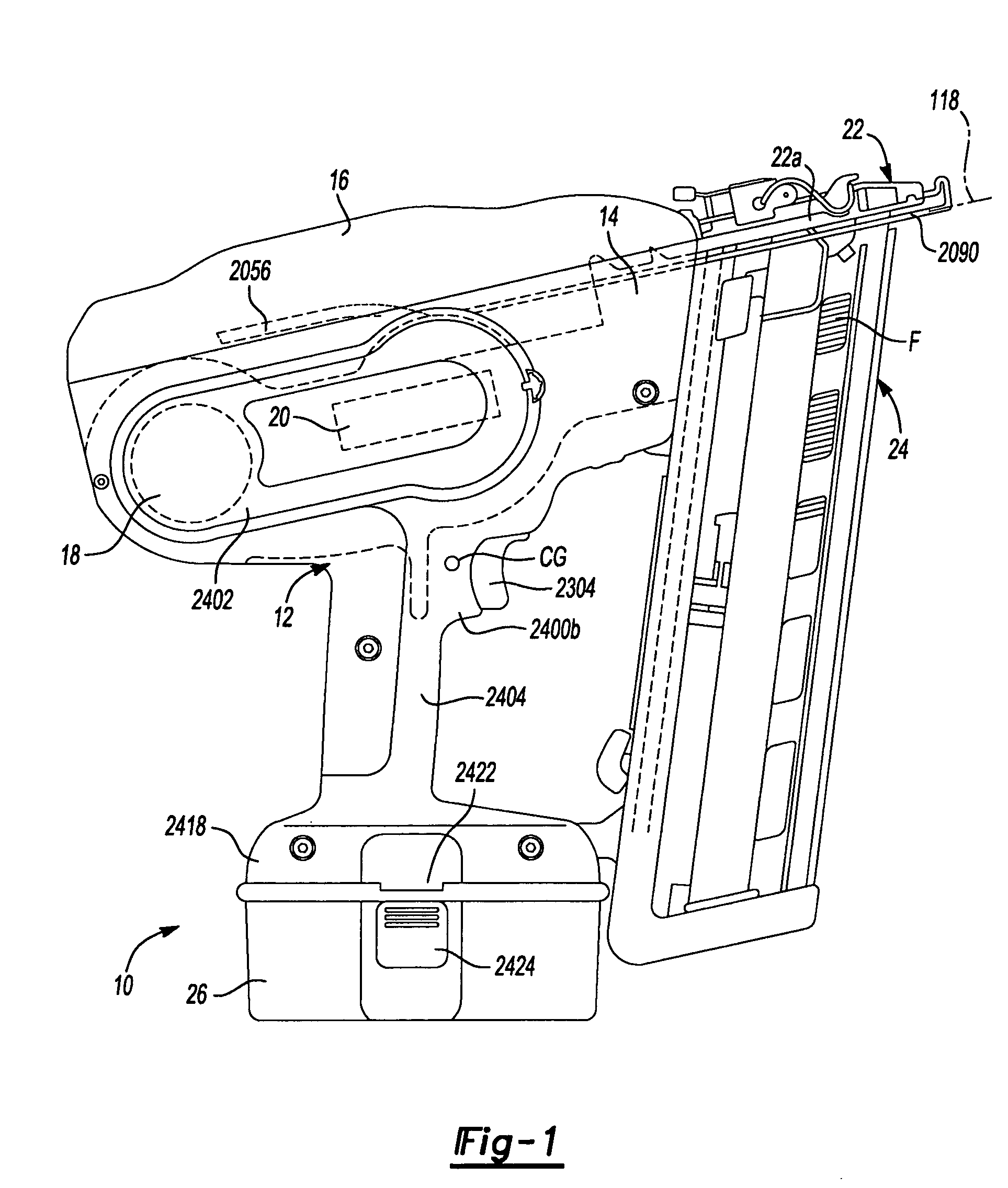
[0095]With reference to FIG. 1 of the drawings, a fastening tool constructed in accordance with the teachings of the present invention is generally indicated by reference numeral 10. The fastening tool 10 may include a housing assembly 12, a backbone 14, a backbone cover 16, an drive motor assembly 18, a control unit 20, a nosepiece assembly 22, a magazine assembly 24 and a battery pack 26. While the fastening tool 10 is illustrated as being electrically powered by a suitable power source, such as the battery pack 26, those skilled in the art will appreciate that the invention, in its broader aspects, may be constructed somewhat differently and that aspects of the present invention may have applicability to pneumatically powered fastening tools. Furthermore, while aspects of the present invention are described herein and illustrated in the accompanying drawings in the context of a nailer, those of ordinary skill in the art will appreciate that the invention, in its broadest aspects,...


PUM

PropertyMeasurementUnit
thicknessaaaaaaaaaa
velocityaaaaaaaaaa
angleaaaaaaaaaa

Abstract

A tool with a driver, which is translatable along a driver axis, and a motor assembly having an electric motor, a flywheel, a roller and an actuator. The electric motor is selectively operable for driving the flywheel. The actuator is selectively operable for translating the roller such that the roller drives the driver against the flywheel to permit energy to be transmitted from the flywheel to the driver. The electric motor is selected to substantially minimize energy losses associated with bringing a mechanical inertial of the motor assembly to a predetermined rotational speed while substantially minimizing an amount of time that is needed to bring the mechanical inertia to the predetermined rotational speed.

Description

CROSS-REFERENCE TO RELATED APPLICATIONS[0001]This application claims priority to U.S. Provisional Patent Application Ser. No. 60 / 559,344 filed Apr. 2, 2004 entitled “Fastening Tool”.INTRODUCTION[0002]The present invention generally relates to the sizing of a motor for a power tool, such as a nailer.[0003]Fastening tools, such as power nailers and staplers, are relatively common place in the construction trades. Often times, however, the fastening tools that are available may not provide the user with a desired degree of flexibility and freedom due to the presence of hoses and such that couple the fastening tool to a source of pneumatic power.[0004]Recently, several types of cordless nailers have been introduced to the market in an effort to satisfy the demands of modern consumers. Some of these nailers, however, are relatively large in size and / or weight, which renders them relatively cumbersome to work with. Others require relatively expensive fuel cartridges that are not re-fillab...

Claims


Application Information

Patent Timeline
Patent Type & Authority Patents(United States)
IPC IPC(8): B25C1/06B25C1/00
CPCB25C1/06
Inventor FORSTER, MICHAEL
Owner BLACK & DECKER INC
Why Eureka
Try Eureka