
Self-drilling pull-through blind rivet and methods of and apparatus for the assembly and setting thereof

a blind rivet and self-drilling technology, which is applied in the direction of screws, threaded fasteners, mechanical equipment, etc., can solve the problems of time-consuming and costly multi-step process, ineffective riveting to secure workpieces, and material of section compromise, etc., to achieve the effect of simplifying the setting operation

Inactive Publication Date: 2008-01-29
NEWFREY
View PDF32 Cites 12 Cited by
  • Summary
  • Abstract
  • Description
  • Claims
  • Application Information

AI Technical Summary

Benefits of technology

[0017]Therefore, it is an object of this invention to provide facility for achieving hole creation and blind riveting in a single step, thereby simplifying the setting operation.
[0018]Another object of this invention is to provide facility for achieving superior cost-effectiveness by using a mandrel with a drill point which is capable of extended use in the setting of many rivets.
[0019]A further object of this invention is to provide facility for comparative saving of time and cost in the formation of workpiece holes, eliminating the need for searching for hole locations, reducing the need for alignment of holes with the mandrel and rivet bodies, and allowing a measured quantity of rivets to be set for each loading of a setting tool.

Problems solved by technology

This multiple step process is time consuming and costly, particularly when each set of aligned holes must be drilled separately and independently from the assembly of the successive rivet bodies within the respective holes.
If the enlarged head was pulled or retracted farther than the prescribed distance, and thereby into the section of the cylindrical portion which is located within the drilled holes, the material of the section would be compromised to the extent that the rivet would be ineffective to secure the workpieces together.
This process is a time consuming and expensive manner of assembling and setting rivets.

Method used


Image

  • Self-drilling pull-through blind rivet and methods of and apparatus for the assembly and setting thereof
  • Self-drilling pull-through blind rivet and methods of and apparatus for the assembly and setting thereof
  • Self-drilling pull-through blind rivet and methods of and apparatus for the assembly and setting thereof

Examples


Embodiment Construction

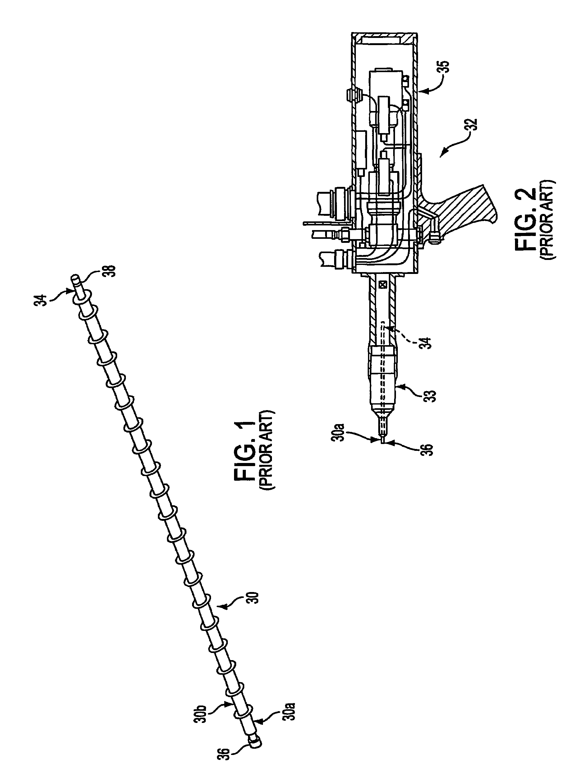
[0048]Referring to FIG. 1 a known unset rivet, referred to herein as a rivet body 30, includes a cylindrical portion having an axial passage, of constant diameter, formed therethrough. A first axial, or forward, end of the rivet body 30 is a continuation of the cylindrical portion, while a second axial, or trailing, end is formed with a flange.

[0049]A known process and a known tool 32 (FIG. 2) can be used by an operator for advancing the rivet bodies 30 into through holes formed in workpieces, and for setting the resulting rivets to secure the workpieces together. Each of the holes in the workpieces is formed with a diameter of a size for receipt of the cylindrical portion of the rivet body therein.

[0050]Initially, a plurality of unset rivet bodies 30 are placed in an axial stack on a mandrel 34. The mandrel 34 is formed with an enlarged setting head 36 at a forward end thereof adjacent the lead, or first, rivet body 30a of the stack. The enlarged head 36 is formed at a diameter lar...


PUM

PropertyMeasurementUnit
diameteraaaaaaaaaa
Rotationaaaaaaaaaa
distanceaaaaaaaaaa

Abstract

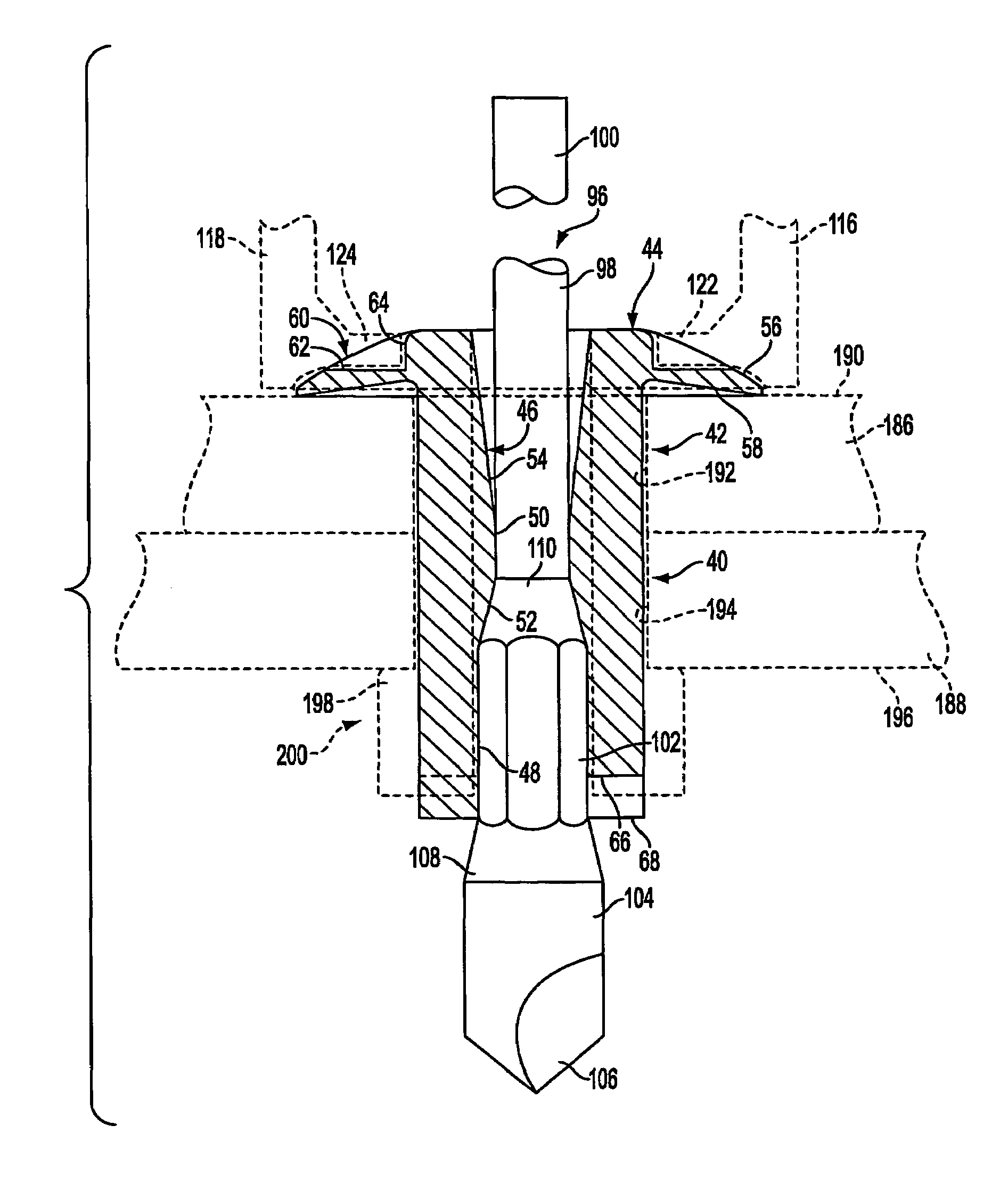
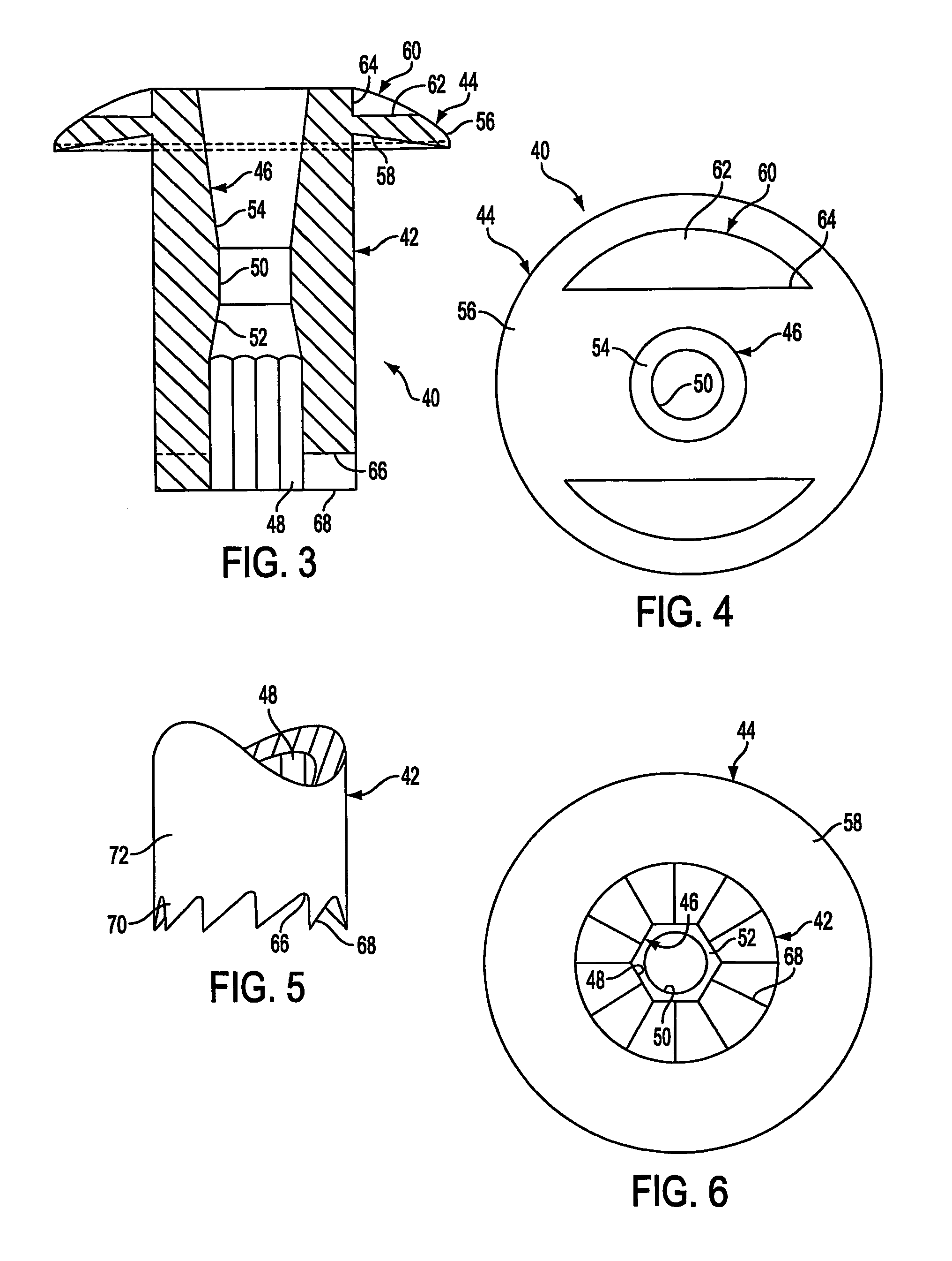
A river body (40) is formed with cutting teeth (68) in a forward edge (66) of the rivet body. A mandrel (96) is formed at a forward end with an enlarged head (104) having a drill point (60) thereon. A plurality of the rivet bodies (40) are stacked on the mandrel (96), with the drill point (60). The rivet body (40a) is rotated and, through rotative coupling, the mandrel (96) is also rotated. The rotating drill point (60) forms pilot holes I workpieces (186) and (188), and the rotating cutting teeth (68) enlarge the pilot holes to form holes (192) and (194), respectively, for receipt of a cylindrical portion (42) of the lead rivet body (40a).

Description

[0001]This application claims the benefit of U.S. Provisional Application No. 60 / 330,875, filed Nov. 1, 2001.BACKGROUND OF THE INVENTION[0002]This invention relates to a self-drilling pull-through blind rivet, and methods of and apparatus for the assembly and setting thereof. In particular, this invention relates to an unset self-drilling pull-through blind rivet which is structured to form a hole in a workpiece for facilitating the locating of the unset rivet therein. This invention further relates to methods of and apparatus for assembling and setting the unset rivet relative to the hole formed thereby.[0003]A known unset rivet, or rivet body, is formed with a cylindrical portion having an axial passage, of constant diameter, formed therethrough. A first axial, or forward, end of the rivet body is a continuation of the cylindrical portion, while a second axial, or trailing, end is formed with a flange.[0004]In one step of a known process for assembling and setting the rivet body t...

Claims


Application Information

Patent Timeline
Patent Type & Authority Patents(United States)
IPC IPC(8): F16B13/04B21J15/04B21J15/26B21J15/34B21J15/36F16B19/08F16B19/10
CPCB21J15/043B21J15/048B21J15/26B21J15/34F16B19/083F16B19/1045B21J15/365Y10T29/53752Y10T29/5373Y10T29/53496
Inventor PEARCE, RICHARD A.SMITH, DANIEL R.STANKO, ROBERT M.
Owner NEWFREY
Learn More