Operational transconductance amplifier

a transconductance amplifier and operation technology, applied in the direction of amplifiers with semiconductor devices only, differential amplifiers, amplifiers with semiconductor devices/discharge tubes, etc., can solve the problem of difficult to precisely process the ac current component containing useful information from the output current following circui

Inactive Publication Date: 2008-01-29
NOVATEK MICROELECTRONICS CORP
View PDF4 Cites 12 Cited by
  • Summary
  • Abstract
  • Description
  • Claims
  • Application Information

AI Technical Summary

Benefits of technology

[0010]An object of the present invention is to provide an operational transconductance amplifier (OTA), which is capable of eliminating the static current component in the output current thereof, so that the following circuit is able to precisely process the AC current component containing information in the output current and to keep the required bandwidth.
[0016]The present invention uses the replica scheme, that is by copying the first differential unit to generate a third differential unit (or a current copy unit) having the substantially same configuration as the first differential unit, and then performs a subtraction between the first output current from the first differential unit and the second output current from the third differential unit (i.e. the current copy unit) in order to eliminate the static current component in the output current, so that the following circuit is able to precisely process the AC current component containing information in the output current. In addition, since the first differential unit and the third differential unit (i.e. the current copy unit) have the same layout, the output current does not vary with the channel length modulation of transistors; thus, the static current component in the output current can be eliminated completely.

Problems solved by technology

A drawback of a conventional operational transconductance amplifier (OTA) to perform a unilateral conversion of signals (voltage-to-current converting) is that a static current component is always companied with the output current therefrom, which though is able to reach a desired converting speed, makes the following circuit difficult to precisely process the AC current component containing useful information from the output current.

Method used


Image

  • Operational transconductance amplifier
  • Operational transconductance amplifier
  • Operational transconductance amplifier

Examples


Embodiment Construction

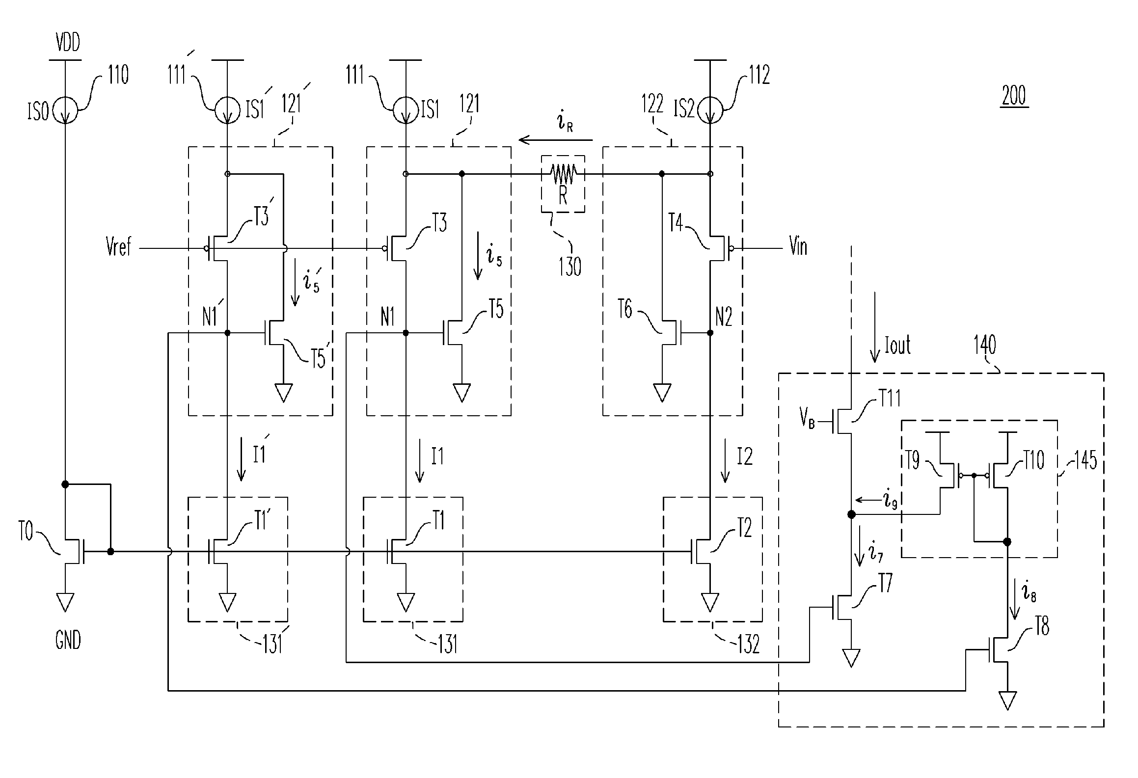
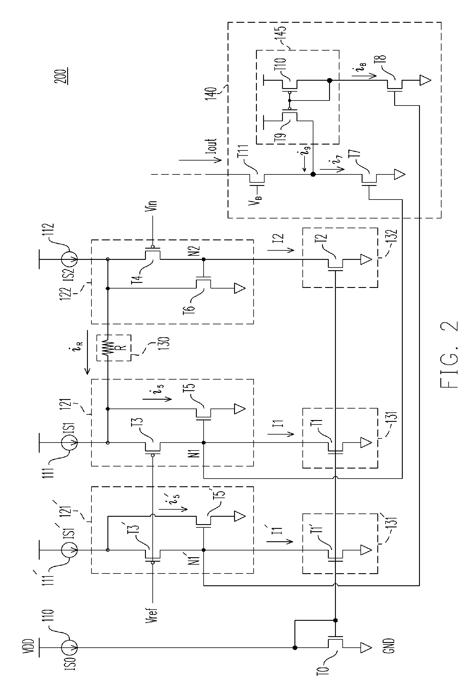
[0020]FIG. 2 is a schematic circuit drawing of an operational transconductance amplifier (OTA) according to an embodiment of the present invention. The OTA is capable of eliminating the static current component contained in the output current thereof and overcoming the drawback of the conventional circuit where the static current component is hard to be eliminated completely since the output current thereof is affected by the channel length modulation of transistors.

[0021]Referring to FIG. 2, an OTA 200 includes a first current source 111, a second current source 112, a third current source 111′, a first current sink 131, a second current sink 132, a third current sink 131′, a first differential unit 121, a second differential unit 122, a third differential unit 121′, a voltage-to-current converting unit 130 and a current subtraction device 140. Wherein, the differential units 121 and 122, the voltage-to-current converting unit 130 and the bias circuit related thereto form an OTA 10...


PUM


Abstract

An operational transconductance amplifier (OTA) includes a first, a second and a third differential units, a voltage-to-current converting unit and a current subtraction device. The first and the second differential units receive a differential input voltage and the voltage-to-current converting unit converts it into an output current. The OTA adopts a replica scheme, that is, by copying the first differential unit to generate a third differential unit and then performs a subtraction between the first output current from the first differential unit and the second output current from the third differential unit in order to eliminate the static current component in the output current. In addition, since the first and the third differential units have the same layout, the output current will not vary with the channel length modulation of transistors, and the static current component in the output current can be eliminated completely.

Description

CROSS-REFERENCE TO RELATED APPLICATION[0001]This application claims the priority benefit of Taiwan application serial no. 95103385, filed on Jan. 27, 2006. All disclosure of the Taiwan application is incorporated herein by reference.BACKGROUND OF THE INVENTION[0002]1. Field of Invention[0003]The present invention relates to an operational transconductance amplifier (OTA), and particularly to an operational transconductance amplifier (OTA) capable of eliminating the static current component contained in the output current thereof.[0004]2. Description of the Related Art[0005]A drawback of a conventional operational transconductance amplifier (OTA) to perform a unilateral conversion of signals (voltage-to-current converting) is that a static current component is always companied with the output current therefrom, which though is able to reach a desired converting speed, makes the following circuit difficult to precisely process the AC current component containing useful information fro...

Claims


Application Information

Patent Timeline
Patent Type & Authority Patents(United States)
IPC IPC(8): H03F3/45
CPCH03F3/45197
Inventor HUANG, CHUN-YI
Owner NOVATEK MICROELECTRONICS CORP
Why Eureka
Try Eureka