Ethernet automatic fiber/copper media selection logic

Active Publication Date: 2008-01-29
MARVELL ASIA PTE LTD
View PDF15 Cites 20 Cited by
  • Summary
  • Abstract
  • Description
  • Claims
  • Application Information

AI Technical Summary

Problems solved by technology

The reprogramming process increases

Method used


Image

  • Ethernet automatic fiber/copper media selection logic
  • Ethernet automatic fiber/copper media selection logic
  • Ethernet automatic fiber/copper media selection logic

Examples


Embodiment Construction

[0026]The following description of the preferred embodiment(s) is merely exemplary in nature and is in no way intended to limit the invention, its application, or uses. For purposes of clarity, the same reference numbers will be used in the drawings to identify similar elements.

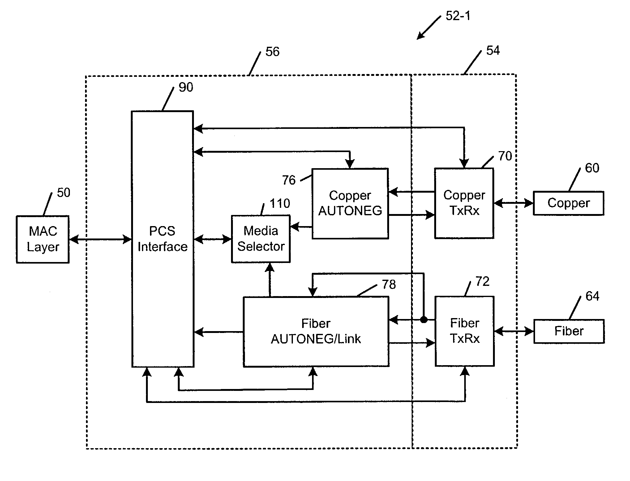
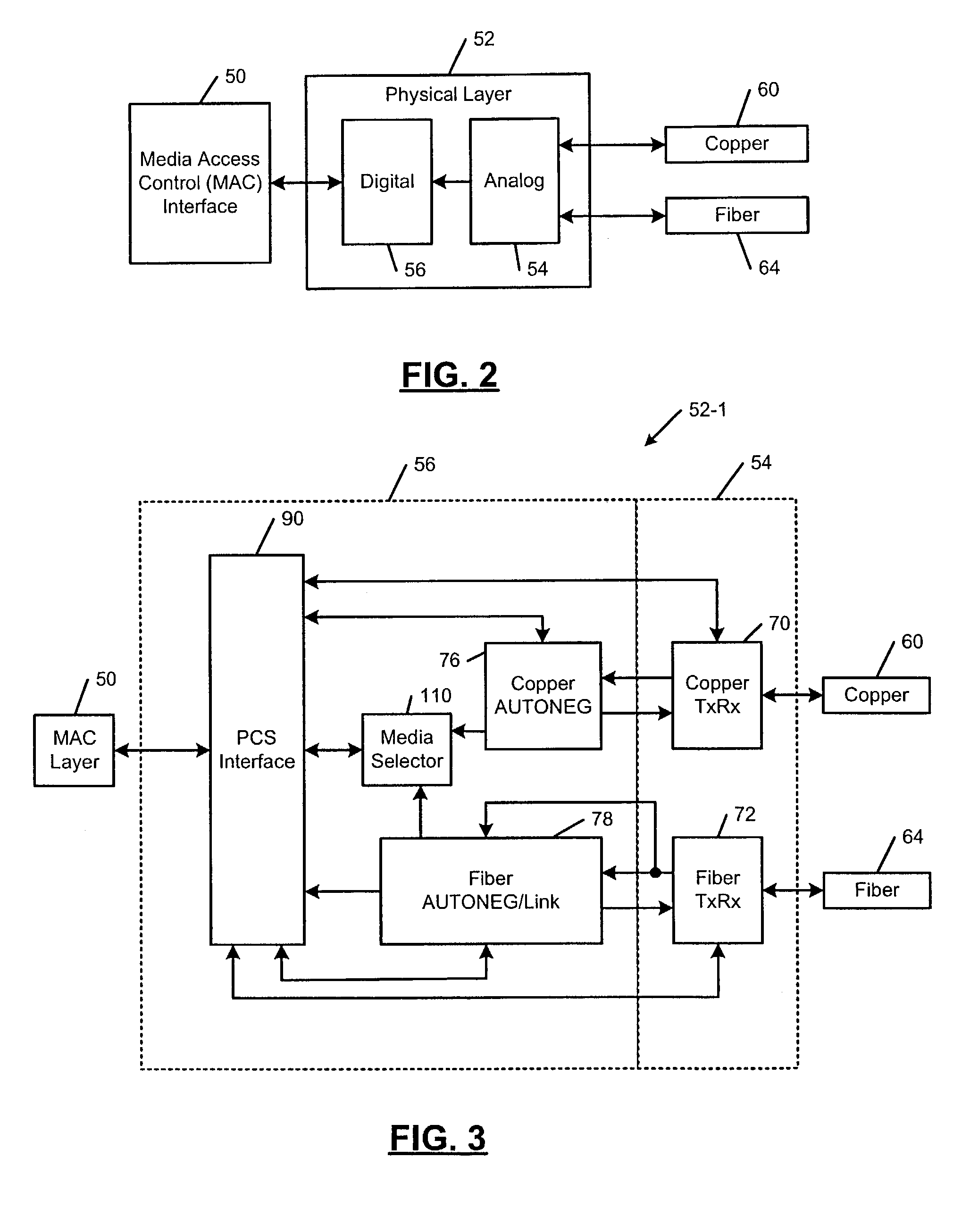
[0027]Referring now to FIG. 2, a media access control (MAC) layer 50 communicates with a physical layer device 52 of a network device. The physical layer device 52 includes analog and digital circuits 54 and 56. In the exemplary embodiment, the analog circuits 54 are physically connected to copper media 60 and / or fiber media 64 using media dependent interfaces (MDI) (not shown in FIG. 2) such as an RJ-45 connector or a fiber connector. Skilled artisans can appreciate that the present invention applies to other types of media such as radio frequency as well.

[0028]In use, the digital circuits 56 of the physical layer device 52 include a physical coding sublayer (PCS) interface. Both the copper and fiber autoneg...


PUM


Abstract

A network device includes a media access controller (MAC) and a physical layer device including an interface that communicates with the MAC, and first and second transceivers. A first autonegotiation circuit attempts to establish a first link using the first transceiver over a first medium. A second autonegotiation circuit attempts to establish a second link using the second transceiver over a second medium. A media selector communicates with the interface and the first and second autonegotiation circuits and enables data flow from the first medium to the MAC using the interface when the link over the first medium is established first. When a preferred medium selector prefers the second medium, the media selector monitors the second medium for a qualified energy detect event. When the qualified energy detect event occurs, the media selector allows a link to be established by the second medium.

Description

CROSS-REFERENCE TO RELATED APPLICATIONS[0001]This application claims the benefit of U.S. Provisional Application No. 60 / 438,933, filed on Jan. 9, 2003, and U.S. patent application Ser. No. 09 / 991,046, filed Nov. 21, 2001, both of which are incorporated herein by reference in their entirety.FIELD OF THE INVENTION[0002]The present invention relates to computer networks, and more particularly to an automatic media selector for Ethernet networks.BACKGROUND OF THE INVENTION[0003]Referring now to FIG. 1, a data link layer 10 of the open systems interconnection (OSI) model includes a logical link control (LLC) layer 12 and a media access control (MAC) layer 14. The LLC layer 12 addresses and exchanges data with a network layer 16. The MAC layer 14 provides an interface between the LLC layer 12 and a physical layer device 18. The MAC layer 14 frames data for transmission over the network and then passes the frame to the physical layer device 18 for transmission as a stream of bits. In other...

Claims


Application Information

Patent Timeline
IPC IPC(8): H04L12/50H04J3/16
CPCH04L12/10H04L12/5692H04L12/5695H04L49/557H04L47/70
Inventor LO, WILLIAMACHARYA, YATIN
Owner MARVELL ASIA PTE LTD
Why Eureka
Try Eureka