Butterfly valve with integral split flapper relief valve

a flapper relief valve and butterfly valve technology, applied in the field of butterfly valves, can solve the problems of affecting the structural integrity of the thin-walled ducts and affecting the operation of the first system

Inactive Publication Date: 2008-02-05
HONEYWELL INT INC
View PDF28 Cites 23 Cited by
  • Summary
  • Abstract
  • Description
  • Claims
  • Application Information

AI Technical Summary

Problems solved by technology

Specifically, if the valve is closed, the ducts of the first system may experience an unwanted buildup of pressure.
Typically, the butterfly valve is opened to allow air to flow through the second system; however, if the control system fails to command the butterfly valve to open, the pressure in the first system may increase to an unacceptable level.
Consequently, the structural integrity of the thin-walled ducts may be compromised.
However, this system, too, may have disadvantages.
Specifically, the parallel duct system includes additional components which may increase the weight and / or manufacturing cost of the aircraft.

Method used


Image

  • Butterfly valve with integral split flapper relief valve
  • Butterfly valve with integral split flapper relief valve
  • Butterfly valve with integral split flapper relief valve

Examples


Embodiment Construction

[0015]The following detailed description of the invention is merely exemplary in nature and is not intended to limit the invention or the application and uses of the invention. Furthermore, there is no intention to be bound by any theory presented in the preceding background of the invention or the following detailed description of the invention.

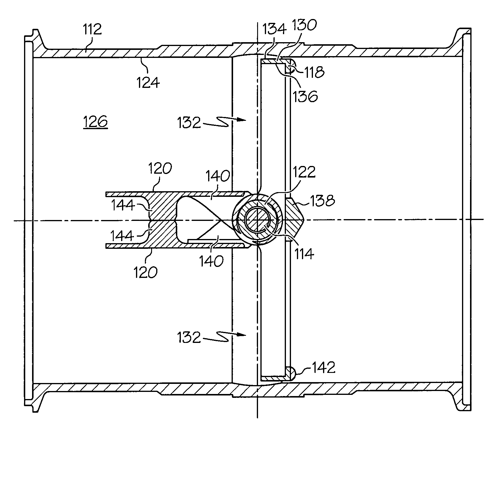
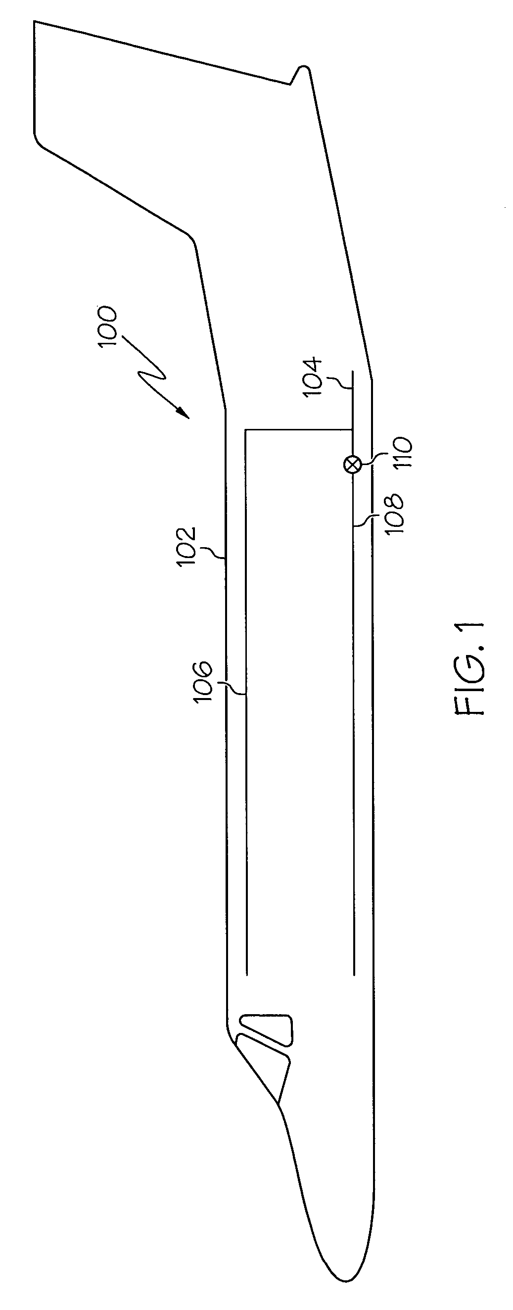
[0016]FIG. 1 is a simplified schematic diagram illustrating an air distribution system 100 disposed within an aircraft 102. The air distribution system 100 includes an inlet duct 104, two outlet ducts 106 and 108, and a valve 110 positioned in duct 108. The inlet duct 102 receives air from an air source, such as, for example, engine bleed air, and the outlet ducts 106 and 108 exhaust air into desired sections of the aircraft 102. In one exemplary embodiment, one outlet duct 106 exhausts air into an aircraft cabin (not shown) and the other outlet duct 108 exhaust airs into an aircraft underfloor. It will be appreciated that although two outle...


PUM


Abstract

A valve is provided that includes a valve housing, a valve element, and a flapper. The valve housing has a passage. The valve element is rotationally mounted in the passage and moveable between an open position and a closed position. Additionally, the valve element has a flow channel extending therethrough. The flapper is coupled to the valve element and moveable between a closed position, to thereby substantially seal the flow channel, and an open position, to thereby unseal the flow channel, the flapper configured to move to the open position when a differential pressure across the flapper reaches a predetermined value.

Description

TECHNICAL FIELD[0001]The present invention relates generally to an aircraft environmental control system, and more particularly to a butterfly valve that allows air to flow through an air duct in the system in the event an unexpected pressure differential is detected across the valve.BACKGROUND[0002]An air distribution system may be used to direct air from one portion of an aircraft to another. In some aircraft configurations, the air distribution system includes an inlet duct that receives air from an air source and two or more outlet ducts that exhaust the received air to a desired area within the aircraft, such as, for example, to an aircraft cabin or an underfloor section of the aircraft. To maintain aircraft weight at certain requirements, the ducts typically have thin walls that are made from lightweight materials, such as wrapped composite. Conventionally, a flow splitter is positioned between the inlet and outlet ducts to distribute the air between the two or more outlet duc...

Claims


Application Information

Patent Timeline
Patent Type & Authority Patents(United States)
IPC IPC(8): F16K15/18
CPCB64D13/02B64D13/04F16K1/223F16K15/038F16K17/0413Y10T137/8803Y10T137/6906Y10T137/7839Y10T137/7877Y10T137/87394
Inventor DENIKE, STUART K.LOUIS, RONALD J.
Owner HONEYWELL INT INC
Why Eureka
Try Eureka