Pulley rotation support apparatus

a technology of supporting apparatus and rotating shaft, which is applied in the direction of vehicle components, synthetic resin layered products, metal layered products, etc., can solve the problems of increasing the axial direction dimension of the above structure, increasing the cost of the composing parts of the structure, and unsatisfactory increase in the axial direction dimension, so as to enhance the effect of improving the durability of the radial ball bearing 14c and enhancing the durability of the radial ball

Inactive Publication Date: 2008-02-05
NSK LTD
View PDF19 Cites 19 Cited by
  • Summary
  • Abstract
  • Description
  • Claims
  • Application Information

AI Technical Summary

Benefits of technology

[0080]According to a calculation made by the inventors of the invention, in the case of the pulley rotation support apparatus of the invention, when compared with a conventional apparatus in which the radii of the inner ring and outer raceways are 0.55 times the diameter of the respective rolling elements, a PV value having a great influence on the seizure life of the grease can be reduced by 5% or more. Here, the PV value is the product of the pressure P of the contact portion between the rolling surfaces of the rolling elements 17 and the inner, outer raceways 19b, 18a and the maximum slip speed V of the respective parts of the present contact ellipse. And, the pressure P increases as the ratios Ri / Da, Ro / Da of the radii of curvature Ri, Ro of the inner ring, outer raceways 19b, 18a with respect to the diameter Da of the respective rolling elements 17 increase, whereas the maximum slip speed V decreases as the above ratios Ri / Da, Ro / Da increase. And, because, when these ratios Ri / Da, Ro / Da are 0.56, the degree of the reduction in the above maximum slip speed has a great influence on the PV value, the PV value is reduced suddenly as described above. Further, according to a calculation made by the inventors of the invention, when compared with the above-mentioned conventional apparatus, the run-up allowance of the rolling element 17 onto the shoulder can be enhanced by 12% or more. Thanks to these calculations, the effects of the invention can be confirmed.
[0081]Also, the foregoing description has been given based on the embodiment of the invention using a four-point-contact-type radial ball bearing 14b in which the rolling surfaces of the rolling elements 17 are contacted with the outer raceway 18a and inner raceway 19b respectively at two points, a total of four points, and the test results thereof. However, even in the case of such a three-point-contact-type radial ball bearing 14c as shown in FIG. 4 in which the rolling surface of a rolling element 17 is contacted with an inner raceway 19c formed in the outer peripheral surface of an inner ring 16c at a point and the rolling surface of the rolling element 17 is contacted with an outer raceway 18a formed in the inner peripheral surface of an outer ring 15a at two points, in case where the embodiment is structured similarly to the above case, similar effects can be obtained. The present inventors conducted a test also on the above three-point-contact-type radial ball bearing 14b and obtained the relationship between the offset quantity and the life ratio. The results of this test, together with those of the previously-described four-point-contact-type radial ball bearing 14b, are shown by a solid b line in FIG. 3. In the intermediate portion of the solid line b of FIG. 3, vertical-direction line segments, which are respectively shown in the portions corresponding to the above-mentioned five kinds of offset quantities δ, express the ranges of variations in the test results regarding to the three-point-contact-type radial ball bearing 14b using two or more test samples for each case, whereas white points on these line segments express the mean values of the respective variation ranges.
[0082]As can be seen clearly from FIG. 3 which shows the above-mentioned test results, in the three-point-contact-type radial ball bearing 14c as well, in case where the offset quantity δ is restricted to 40% or less of the pitch circle diameter Dp of the radial ball bearing 14c, there can be secured the life that is practically necessary, thereby being able to realize a structure which can withstand practical use. On the other hand, in case where the offset quantity δ exceeds 40% of the pitch circle diameter Dp of the radial ball bearing 14c, the durability of the radial ball bearing 14c is worsened suddenly. Also, in case where the offset quantity δ is restricted to 20% of or less than the pitch circle diameter Dp of the radial ball bearing 14c, the durability of the radial ball bearing 14c can be enhanced up to a value which is 12 times the practically necessary value or more. Further, in case where the offset quantity δ is restricted to 10% of or less than the pitch circle diameter Dp of the radial ball bearing 14c, the durability of the radial ball bearing 14c can be enhanced up to a value which is about 13 times the practically necessary value or more. As can be seen obviously from such FIG. 3, when the lives of the two kinds of radial ball bearings are compared with each other, the life of the three-point-contact-type radial ball bearing 14c is longer than the life of the four-point-contact-type radial ball bearing 14b.
[0083]However, when a moment load is applied to driven pulleys respectively supported by these two rolling element bearings 14c, 14b, the inclination angle of the driven pulley supported by the three-point-contact-type radial ball bearing 14c is larger than the inclination angle of the driven pulley supported by the four-point-contact-type radial ball bearing 14b. Therefore, the life of an endless belt arranged on the driven belt supported by the three-point-contact-type radial ball bearing 14c is shorter than the life of an endless belt arranged on the driven belt supported by the four-point-contact-type radial ball bearing 14b. For this reason, actually, according to uses, while taking into account the balance between the lives of the endless belts of the radial ball bearings 14c, 14b, one of the three-point-contact-type or four-point-contact-type radial ball bearing 14c, 14b can be selected.
[0084]Also, a three-point-contact-type radial ball bearing is not limited to the above-mentioned structure shown in FIG. 4 but, in the case of such a three-point-contact-type radial ball bearing 14d as well as shown in FIG. 5 in which the rolling surface of a rolling element 17 is contacted with an outer raceway 18b formed in the inner peripheral surface of an outer ring 15b at a point and the rolling surface of the rolling element 17 is contacted with an inner raceway 19b formed in the outer peripheral surface of an inner ring 16b at two points, when the embodiment is structured similarly to the three-point-contact-type radial ball bearing 14c, there can be obtained similar effects.
[0085]The present embodiment is based on the Japanese patent application (Patent Application 2002-015428) filed on Jan. 24, 2002 and thus the contents thereof are incorporated into the present embodiment for reference.

Problems solved by technology

However, use of the above double-row radial ball bearing 5 inevitably increases the axial-direction dimension of the above structure.
The rotation support part of the above driven pulley 4, in many cases, must be disposed in a limited space and thus the increase in the axial-direction dimension is not desirable.
Also, the increase in the axial-dimension increases the costs of the composing parts of the structure.
As a result of this, not only the durability of the above radial ball bearing is insufficient but also great partial wear is easy to occur in the endless belt 11 arranged on the above driven pulley 4.
However, in the case of the conventional structures, since the factors and elements of the respective parts thereof are not examined to the full, there cannot be always obtained a sufficient effect.
However, when the auxiliary machine is improved in the rotation thereof and the like, a rolling element bearing for supporting a pulley for the auxiliary machine is easy to generate heat, which reduces the seizure life (deterioration life) of grease.
Also, since an excessively large moment load is applied to the rolling element bearing, the rolling elements are easy to run up onto the shoulder portions of an outer raceway and an inner raceway.
Therefore, in a rolling element bearing to be used in the machine such as an engine auxiliary machine which is required for an increase in the rotation and capacity thereof as well as is required for a reduction in the size thereof, when no consideration is given at all to an increase in the seizure life of the grease and a run-up allowance of the rolling element (a ratio which expresses the difficulty for the rolling element to run up onto the shoulders of the raceways), there is a possibility that these performances of the rolling element bearing can be insufficient.

Method used


Image

  • Pulley rotation support apparatus
  • Pulley rotation support apparatus
  • Pulley rotation support apparatus

Examples


first embodiment

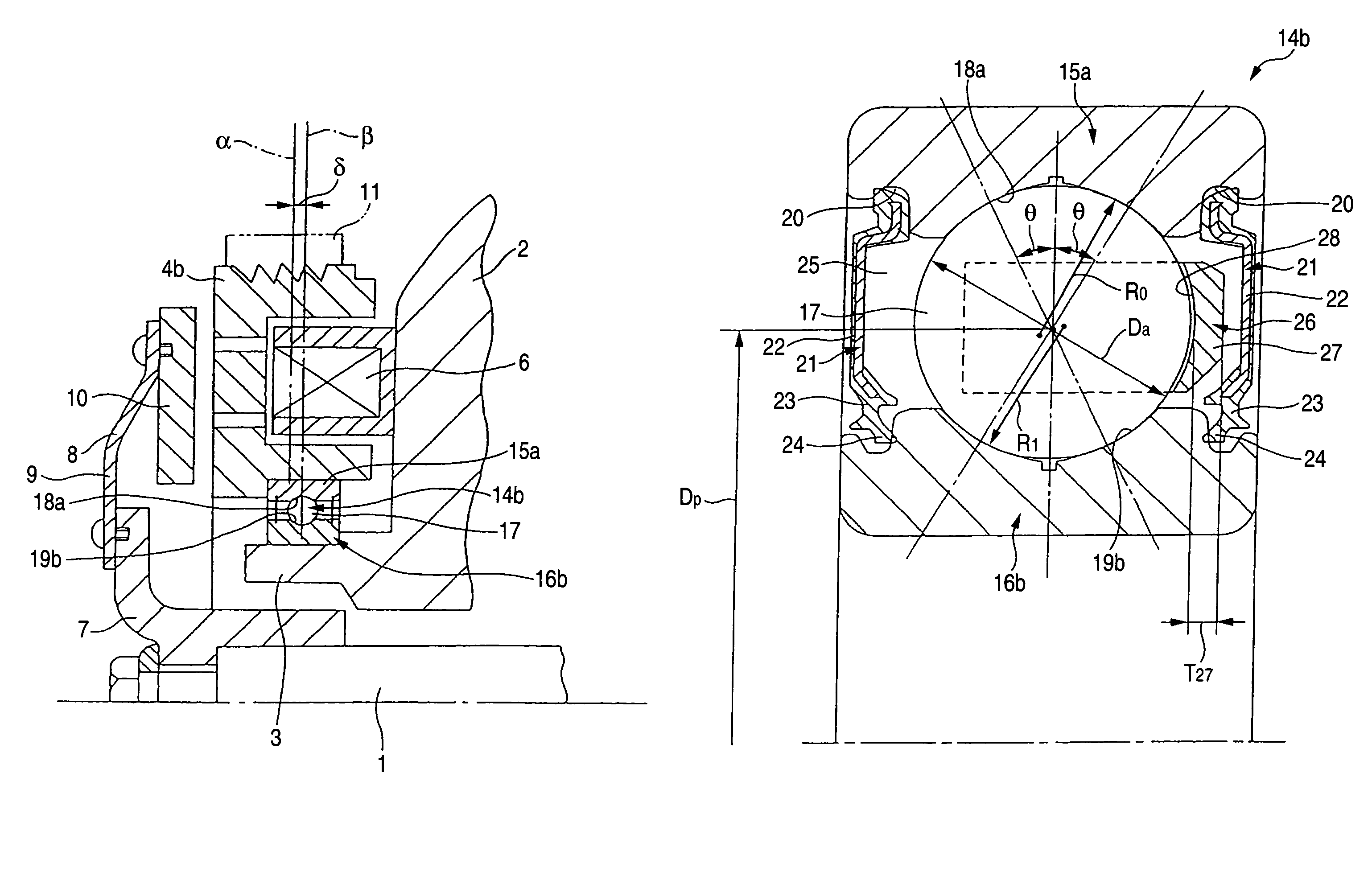
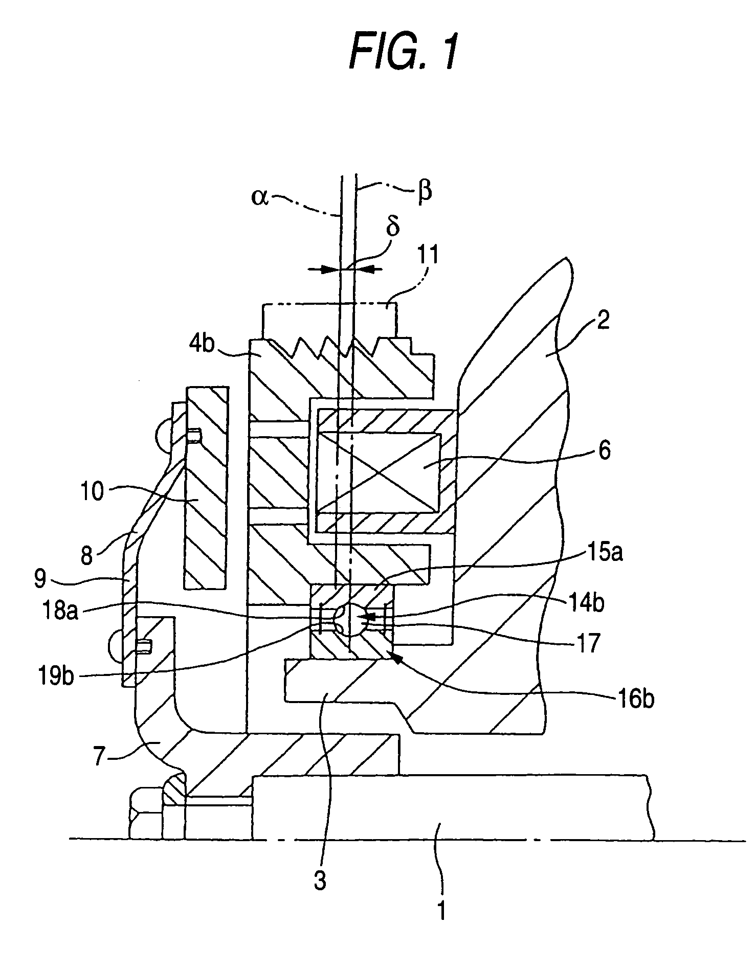
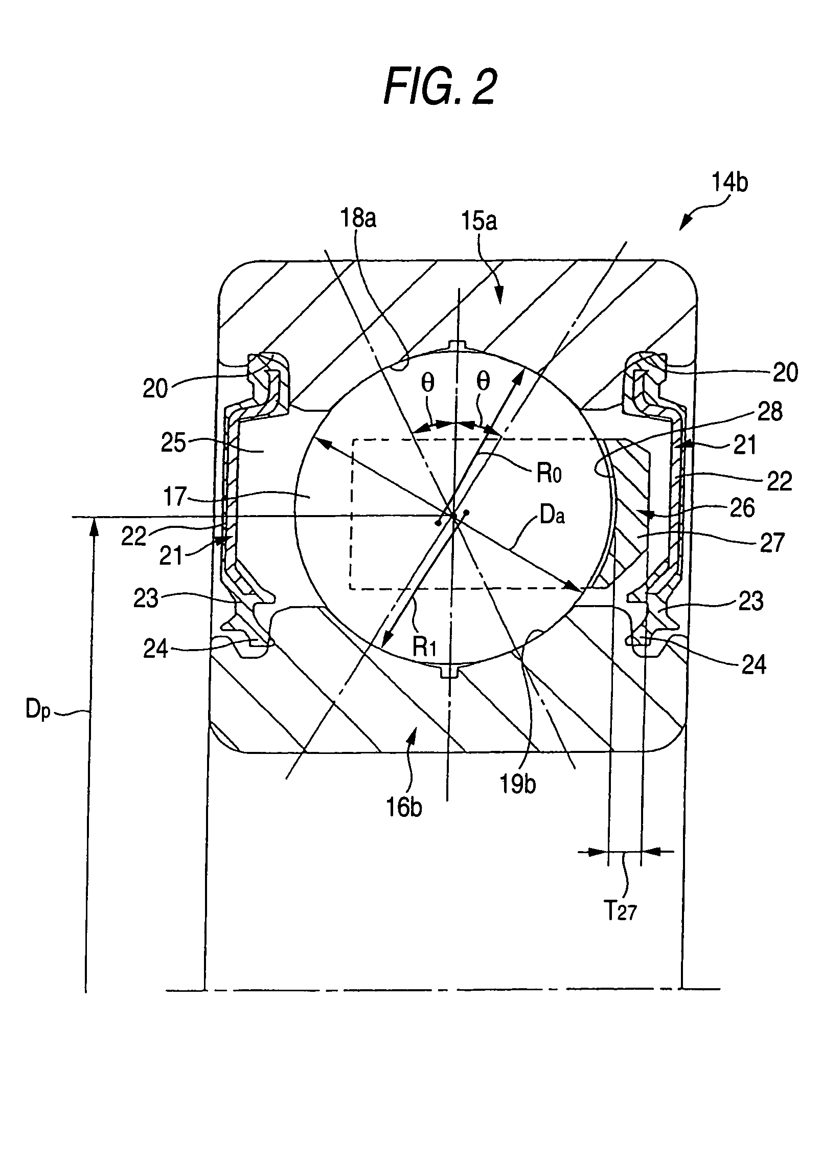
[0065]Now, FIGS. 1 and 2 show the mode for carrying out the invention, which corresponds to the first aspect. By the way, the present embodiment is characterized in that, in a structure using a four-point-contact-type radial ball bearing 14b as a rolling bearing in a rotation support part for a driven pulley 4b, not only the factors of the radial ball bearing 14b are restricted properly but also the position relationship between this radial ball bearing 14b and the above driven pulley 4b is restricted properly in connection with the factors of the radial ball bearing 14b, thereby being able to secure the durability of this radial ball bearing 14b and an endless belt 11 arranged on and over the above driven pulley 4b. The structures and operations of the other parts of the present embodiment are similar to those of the conventional structure shown in the previously described FIG. 32. Therefore, the same designations are given to the same parts and thus the duplicate description there...

second embodiment

[0086]Now, FIGS. 7 to 11 show a second embodiment according to the mode for carrying out the invention, corresponding to the first aspect. By the way, the present embodiment is characterized in that the opening direction of a pocket 44 of a retainer 45 used in a single-row ball bearing 40 is set to thereby decide a direction in which a radial load F is applied to a bearing central line β, and the radial load F offset with respect to the bearing central line β is applied to thereby allow grease existing around the periphery of the load area during the operation of the bearing to circulate actively from an inner raceway on the opening side of the pocket 44 of the retainer 45 to an outer raceway.

[0087]The single-row ball bearing 40 according to the second embodiment is a four-point-contact-type ball bearing with its inner and outer rings each having a Gothic-arch-like shape; and it comprises an inner ring 41, an outer ring 42, two or more balls (rolling elements) 43 interposed between ...

third embodiment

[0135]Now, FIGS. 12 and 13 show the mode for carrying out the invention. By the way, the present embodiment is characterized by an improvement in the shape of a seal plate 91a which allows grease charged into the space 92 of a rolling bearing 81a with a seal plate to circulate within the space 92 to thereby delay the degradation of the grease used to lubricate the rolling contact portions of an inner raceway 82 and outer raceway 84 with the rolling surfaces of the respective rolling elements 86.

[0136]Of the inner surfaces of the seal plate 91a constituting the rolling bearing 81a with a seal plate according to the present embodiment, the near-to-outside-diameter portion close to the inner peripheral surface of an outer ring 85 (which exists in the portion of the inner surface of the seal plate 91a slightly nearer to the inside diameter portion than the inner peripheral surface of the outer ring) is formed as an outside-diameter-side inclined surface 98 which is inclined inwardly in ...


PUM

PropertyMeasurementUnit
rest anglesaaaaaaaaaa
weight percentaaaaaaaaaa

Abstract

An endless belt (11) to be provided on a driven pulley (4b) and a pulley rotation support apparatus for supporting the driven pulley (4b). In the pulley rotation support apparatus, there is used a three-point-contact-type or four-point-contact-type radial ball bearing (14b). An offset quantity δ, which is an axial-direction distance between the center α of a radial load applied from the endless belt (11) to the driven pulley (4b) and the center position β of the radial ball bearing (14b), is set 40% or less of the pitch circle diameter of the radial ball bearing (14b). The radial clearance of this radial ball bearing (14b) is set 0.2% or less of the above pitch circle diameter.

Description

TECHNICAL FIELD[0001]A pulley rotation support apparatus according to the invention is used to support a pulley, on which there is disposed a belt to be driven and rotated by an engine for e.g. a car, on a fixed part of the car in such a manner that the pulley can be rotated with respect to the fixed part.BACKGROUND ART[0002]Conventionally, an automatic tensioner has been used in order to adjust the tensile force of a timing belt or an auxiliary machine driving belt used in a car engine, and the thus-adjustable belt has been used to drive an auxiliary machine such as a compressor. And, in a rotation support part for a pulley for use in the automatic tensioner or a driven pulley for driving the above auxiliary machine, there is supported such pulley on a fixed part using a rolling bearing in such a manner that the pulley can be rotated with respect to the fixed part.[0003]For example, FIG. 32 shows a first example of conventional structures in which a double-row rolling element beari...

Claims


Application Information

Patent Timeline
Patent Type & Authority Patents(United States)
IPC IPC(8): F16C33/76F16H55/36B32B7/12B62M9/00B32B15/08B32B27/28C08G73/10C08G73/14H05K1/03H05K3/38
CPCB32B7/12B32B15/08B32B27/28F16C19/166F16C33/78H05K1/0346H05K3/389F16C2361/63F16C33/7853
Inventor TANABE, KOUICHIMIYAGAWA, TAKAYUKITANIGUCHI, MASATO
Owner NSK LTD
Why Eureka
Try Eureka