

Pulley rotatingly supporting device
- Summary
- Abstract
- Description
- Claims
- Application Information
AI Technical Summary
Benefits of technology
Problems solved by technology
Method used
Image

Examples
first embodiment
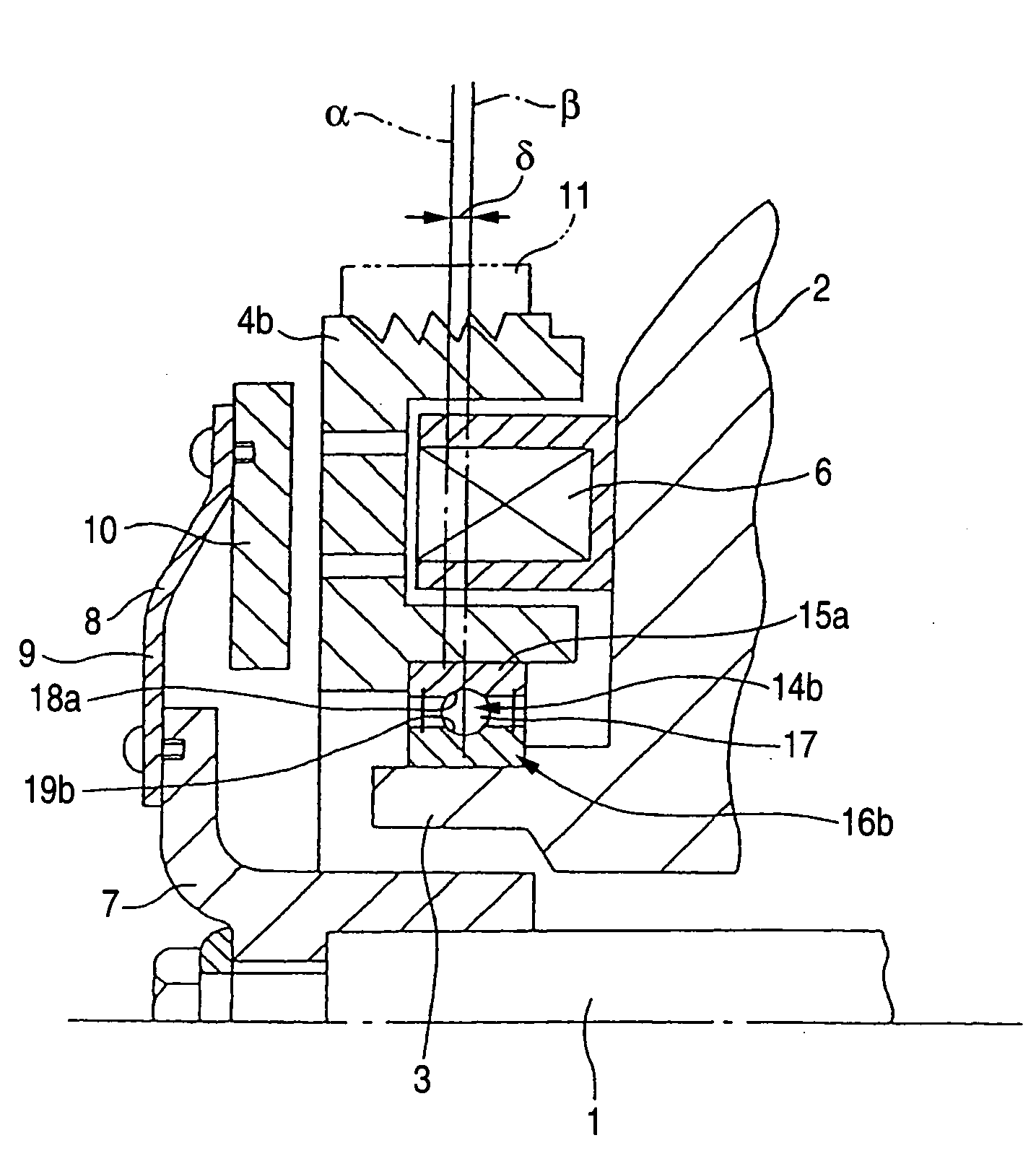
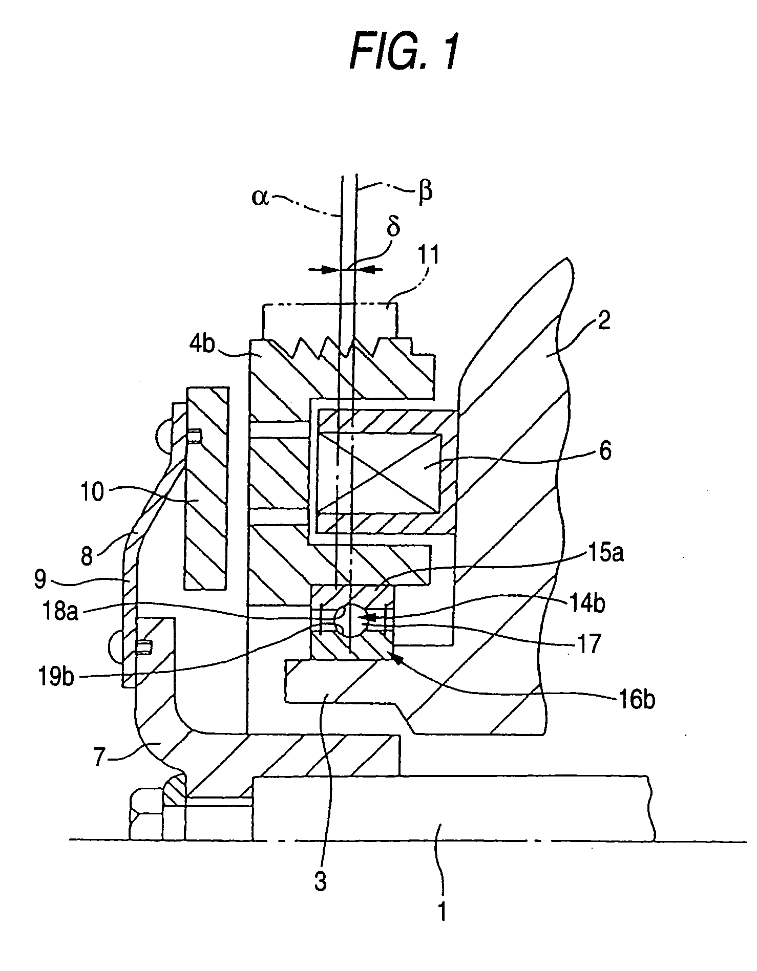
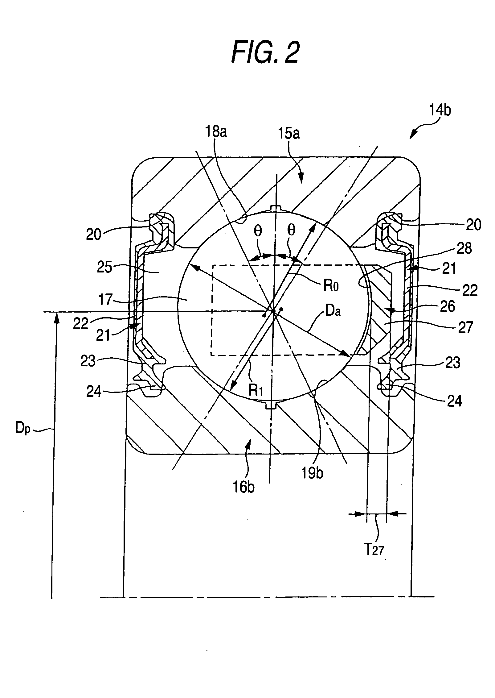
[0065] Now, FIGS. 1 and 2 show the mode for carrying out the invention, which corresponds to claim 1. By the way, the present embodiment is characterized in that, in a structure using a four-point-contact-type radial ball bearing 14b as a rolling bearing in a rotation support part for a driven pulley 4b, not only the factors of the radial ball bearing 14b are restricted properly but also the position relationship between this radial ball bearing 14b and the above driven pulley 4b is restricted properly in connection with the factors of the radial ball bearing 14b, thereby being able to secure the durability of this radial ball bearing 14b and an endless belt 11 arranged on and over the above driven pulley 4b. The structures and operations of the other parts of the present embodiment are similar to those of the conventional structure shown in the previously described FIG. 32. Therefore, the same designations are given to the same parts and thus the duplicate description thereof is om...
second embodiment
[0085] The present embodiment is based on the Japanese patent application (Patent Application 2002-015428) filed on Jan. 24, 2002 and thus the contents thereof are incorporated into the present embodiment for reference. Now, FIGS. 7 to 11 show a second embodiment according to the mode for carrying out the invention, corresponding to Claim 1. By the way, the present embodiment is characterized in that the opening direction of a pocket 44 of a retainer 45 used in a single-row ball bearing 40 is set to thereby decide a direction in which a radial load F is applied to a bearing central line β, and the radial load F offset with respect to the bearing central line β is applied to thereby allow grease existing around the periphery of the load area during the operation of the bearing to circulate actively from an inner raceway on the opening side of the pocket 44 of the retainer 45 to an outer raceway.
[0086] The single-row ball bearing 40 according to the second embodiment is a four-point-c...
third embodiment
[0134] Now, FIGS. 12 and 13 show the mode for carrying out the invention. By the way, the present embodiment is characterized by an improvement in the shape of a seal plate 91a which allows grease charged into the space 92 of a rolling bearing 81a with a seal plate to circulate within the space 92 to thereby delay the degradation of the grease used to lubricate the rolling contact portions of an inner raceway 82 and outer raceway 84 with the rolling surfaces of the respective rolling elements 86.
[0135] Of the inner surfaces of the seal plate 91a constituting the rolling bearing 81a with a seal plate according to the present embodiment, the near-to-outside-diameter portion close to the inner peripheral surface of an outer ring 85 (which exists in the portion of the inner surface of the seal plate 91a slightly nearer to the inside diameter portion than the inner peripheral surface of the outer ring) is formed as an outside-diameter-side inclined surface 98 which is inclined inwardly i...
PUM
| Property | Measurement | Unit |
|---|---|---|
| Fraction | aaaaa | aaaaa |
| Fraction | aaaaa | aaaaa |
| Diameter | aaaaa | aaaaa |
Abstract
Description
Claims
Application Information