Substrate treatment process and apparatus

a technology of substrate and treatment process, applied in the direction of lighting and heating apparatus, chemistry apparatus and processes, cleaning using liquids, etc., can solve the problems of damage spreading from such surface roughening, damage to the pattern, and damage to the surface, so as to minimize the reduction of electrical characteristics of the device, no substantial pollutant load on the environment nor damage to the pattern. , the effect of improving production yield

Inactive Publication Date: 2006-01-10
M FSI
View PDF16 Cites 7 Cited by
  • Summary
  • Abstract
  • Description
  • Claims
  • Application Information

AI Technical Summary

Benefits of technology

[0012]An object of the present invention is, therefore, to provide a substrate treatment process and apparatus, which can achieve similar cleaning effects as the conventional techniques without needing use of sulfuric acid, hydrogen peroxide, ammonia, oxygen plasma and / or the like as an essential requirement and without causing production of harmful vapor, incorporation of a metal component such as iron, damage to a substrate, a pollutant load on the environment, or the like.
[0025]The processes according to the present invention use only ozone and hydrogen waters or ozone-hydrogen water to remove unnecessary resist after formation of an arrangement of electrical component parts or a circuit, that is, a pattern on a substrate, and therefore, are low-cost processes which give neither substantial pollutant load on the environment nor damage to the pattern. The processes of the present invention are expected to minimize corrosion-related reductions in electrical characteristics of a device and hence to bring about improvements in production yield, so that they make it possible to lower the running cost of a semiconductor fabrication system and also to improve the safety. As is appreciated from the foregoing, the series of treatments in the cleaning step subsequent to the stripping of a resist, said treatments making use of ozone and hydrogen waters or ozone-hydrogen water, can solve various problems in future manufacturing business, such as energy conservation, owing to a reduction in the pollutant load on the environment and simplification of the device forming steps.
[0026]Fine particles existing on a substrate, such as pieces of a resist, have heretofore been removed using sulfuric acid, ammonia, hydrogen peroxide, organic solvent or the like. As the processes of the present invention do not use these chemical solutions, they do not significantly corrode the arrangement of component parts or the interconnecting conductive material. Damage to the arrangement of the component parts or the circuits is thus reduced, leading to improvements, for example, in the reliability of performance of the device. This can obviate a step for the prevention of corrosion or, even if such a step is still needed, the cost of materials employed for such treatments can be reduced. On the other hand, the reduction in the corrosion to the interconnecting conductive material leads a reduction in the electrical resistance of the device, a reduction in the power consumption by the device, and a higher speed in the performance of the device.
[0027]The conventional treatment in which hydrogen water is used in an activated form is said to permits removal of very fine particles. The processes of the present invention have a significance in that owing to the above-described combination of the treatment with ozone water and the treatment with hydrogen water or the above-described use of ozone-hydrogen water, steps ranging, for example, from the stripping of a resist or the like to the subsequent cleaning can be conducted together without using a conventional chemical solution of high purity such as sulfuric acid. Use of the processes and apparatus according to the present invention, which have enabled it, has made it possible for the first time to perform the treatment.
[0028]According to the present invention, the resist stripping step and the cleaning step can be conducted together. This has made it unnecessary to carry each substrate from one processing step to another, thereby brining about merits such as a reduction in the risk to contact a dangerous chemical solution and a reduction in the risk to contact a pollutant. Owing to these merits, the single-step treatment can contribute to a reduction in cost.

Problems solved by technology

The cleaning with ozone water subsequent to ashing as disclosed in JP 10-2985 89 A involves a potential problem in that a substrate may be damaged as the plasma ashing is performed with high energy, and the cleaning treatment with the ozone water is accompanied by a further potential problem in that the damage may be deteriorated.
In addition, surface roughening may also occur by a cause other than the plasma ashing, and the cleaning with the ozone water has a potential problem in that damage may be spread from such surface roughening.
The concentration of ozone in conventional ozone water, which is available at room temperature under the surrounding atmospheric pressure, is its saturated concentration at the maximum, and therefore, this cleaning process is not considered to be effective for the removal of organic matter still remaining after dry ashing of a resist.
Of these conventional processes, the wet processes use one or more chemicals such as sulfuric acid, hydrogen peroxide and / or ammonia upon treatment, and may develop one or more defects in a formed pattern due to formation of sulfuric acid vapor, which gives detrimental effects such as corrosion to a substrate, or due to incorporation of a metal component such as iron due to the use of ammonia.
Avoidance of these problems leads to a further problem that subsequent to the treatment, a great deal of cleaning water is needed, resulting in a substantial load of effluent on the environment.
On the other hand, the use of oxygen plasma in the dry processes involves a problem in that a substrate, which is chemically sensitive, and a pattern formed on the substrate may be damaged because the plasma has high energy.

Method used


Image

  • Substrate treatment process and apparatus
  • Substrate treatment process and apparatus
  • Substrate treatment process and apparatus

Examples


example 1

Striping Treatment of Resist with Ozone Water

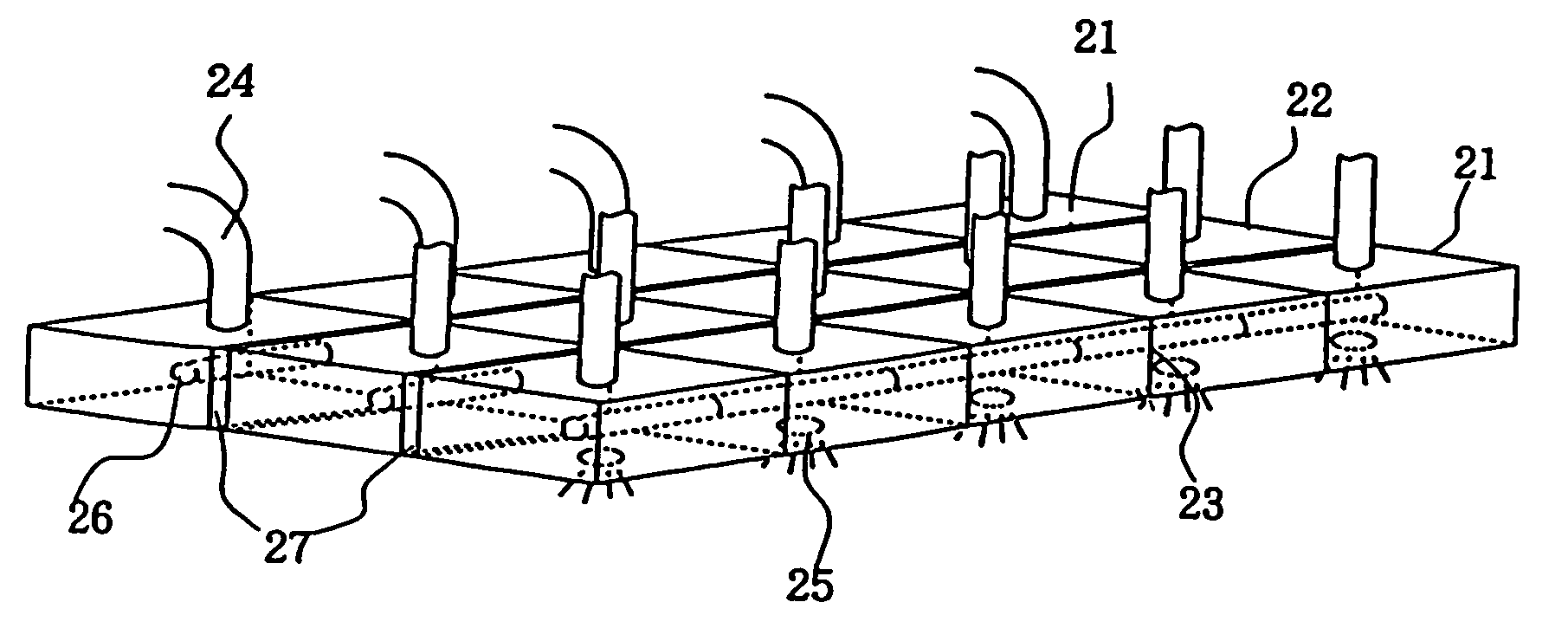
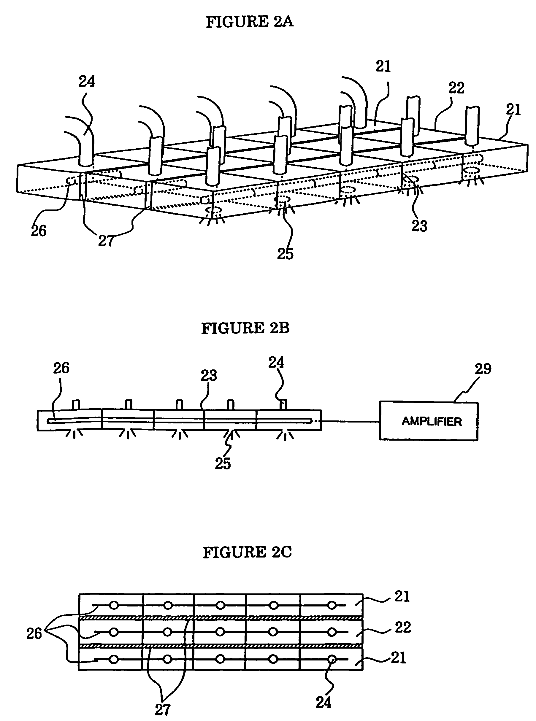
[0071]The ozone water for treating each sample was ejected from the nozzle unit shown in FIGS. 2A–2C. Treatment conditions for that treatment step are shown in Table 3. In addition, the thickness values of the resist film before and after the treatment are also shown. The ejection rate of ozone water at that time was 10 mL / min per cm2 of substrate area. Through the outlets other than the outlets for the ozone water, ultrapure water which had been heated to 50° C. by a quartz heater was ejected onto each substrate. Over the ultrapure water, ozone water was ejected at the same ejection rate as that described above.

[0072]

TABLE 3Conditions for Resist Stripping with Ozone Water (60 ppm),and Results of StrippingSampleABCTreatment solutionOzone waterOzone waterOzone waterOzone concentration 60 ppm 60 ppm 60 ppmTreatment time 12 min 15 min 10 minTreatment temperature  50° C.  50° C.  50° C.Rotational speed1500 rpm1500 rpm1500 rpmResist film thick...

example 2

Resist Stripping Treatment by SPM Treatment

[0077]SPM treatment for the treatment of each sample was conducted in a conventional chemical bath cleaning equipment. Treatment conditions for that treatment step are presented in Table 6. The thickness values of each resist film before and after the treatment are also shown.

[0078]

TABLE 6Conditions for Resist Stripping by SPM, and Results of StrippingSampleABCTreatment solutionSPMSPMSPMMixing ratio (volume4:14:14:1ratio)(sulfuric acid:hydrogen peroxide)Treatment time7 min7 min5 minTreatment temperature100° C.100° C.100° C.Resist film thickness7000 Å7000 Å7000 Å(before treatment)Resist film thicknessStrippedStrippedStripped(after treatment)completelycompletelycompletely

[0079]After the stripping of the resist, each substrate was observed under the microscope equipped with the laser beam source. No resist film was observed to be remaining on the surface of the substrate. Fine particles remaining on the substrate shortly after the stripping of...

example 3

Resist Stripping Treatment by SPM Treatment

[0084]SPM treatment for the treatment of each sample was conducted in the conventional chemical bath cleaning equipment. Treatment conditions for that treatment step are presented in Table 9. The thickness values of the resist film before and after the treatment are also shown.

[0085]

TABLE 9Conditions for Resist Stripping by SPM, and Results of StrippingSampleABCTreatment solutionSPMSPMSPMMixing ratio (volume4:14:14:1ratio)(sulfuric acid:hydrogen peroxide)Treatment time10 min13 min13 minTreatment temperature100° C.125° C.125° C.Resist film thickness7000 Å7000 Å7000 Å(before treatment)Resist film thicknessStrippedStrippedStripped(after treatment)completelycompletelycompletely

[0086]After the stripping of the resist, the substrates were observed under the microscope equipped with the laser beam source. Practically no fine particles were observed on the surface of each substrate, but some of the samples were observed to carry a great number of f...


PUM

PropertyMeasurementUnit
frequencyaaaaaaaaaa
frequencyaaaaaaaaaa
temperatureaaaaaaaaaa

Abstract

A substrate treatment apparatus comprises a treatment vessel, a substrate holder for rotating the substrate in a horizontal plane in the treatment vessel, a nozzle unit arranged in an upper part of the treatment vessel such that a liquid is downwardly fed, a feed line for feeding the liquid to the nozzle unit, and a chamber enclosing therein the apparatus in its entirety. The nozzle unit is constructed in a form of a bar such that as viewed in plan, the liquid ejected from the nozzle unit reaches the substrate with an area range having a length not smaller than a diameter of the substrate and a width smaller than the diameter of the substrate.

Description

CROSS-REFERENCE TO RELATED APPLICATIONS[0001]This application is a divisional of U.S. application Ser. No. 09 / 742,423 filed Dec. 22, 2000, now U.S. Pat. No. 6,743,301 and further is based upon and claims the benefit of priority from the prior Japanese Patent Application No. 367923 / 1999, filed Dec. 24, 1999, and the prior Japanese Patent Application No. 307029 / 2000, filed Oct. 6, 2000, the entire contents of each of which are hereby incorporated herein by reference.BACKGROUND OF THE INVENTION[0002]a) Field of the Invention[0003]This invention relates to a process and apparatus for treating a variety of substrates—such as wafers, glass substrates or ceramic substrates for forming semiconductor devices thereon (hereinafter called “substrates”)—by cleaning off, subsequent to formation of a fine arrangement of electrical component parts or a circuit (hereinafter may be commonly called “pattern”) on the substrates, foreign matter such as organic matter remaining on the substrates and othe...

Claims


Application Information

Patent Timeline
Patent Type & Authority Patents(United States)
IPC IPC(8): B08B3/00B08B3/12H05K3/26
CPCB08B3/12Y10S438/905Y10S134/902H05K3/26
Inventor MATSUNO, KOUSAKUIGA, MASAO
Owner M FSI
Why Eureka
Try Eureka