Hydrodynamic bearing type rotary device and recording and reproduction apparatus including the same

a technology of hydrodynamic bearings and rotary devices, which is applied in the direction of bearings, shafts and bearings, rotary bearings, etc., can solve the problems of poor bubble discharge, failure of hydrodynamic bearing type rotary devices, and inability to obtain desired bearing properties

Active Publication Date: 2009-05-05
PHC HLDG CORP
View PDF6 Cites 7 Cited by
  • Summary
  • Abstract
  • Description
  • Claims
  • Application Information

AI Technical Summary

Benefits of technology

[0022]In this case, the capillary force is applied to the lubricating fluid from the communication hole to the first fluid reservoir. Thus, the bubbles can move from the first fluid reservoir to the communication hole easily. Accordingly, it is ensured that the bubbles are discharged from the bearing portion.
[0065]In this recording and reproduction apparatus, similar effects as those of the hydrodynamic bearing type rotary device according to the fifteenth invention can be achieved.

Problems solved by technology

However, when there is a bubble in the lubricating fluid, shortage of an oil film may occur in the radial bearing portion and the thrust bearing portion, which may result in deterioration in NPPRO and the like, and a desired bearing property cannot be obtained.
Further, the shaft or the sleeve may slide directly on the surface of the other, causing a failure of the hydrodynamic bearing type rotary device.
This means that taking only the circulating force generated by a pumping pressure into account cannot completely solve the problem of poor discharge of the bubbles.
It is difficult to predict the behavior of the bubbles based on just the conventional wisdom.

Method used


Image

  • Hydrodynamic bearing type rotary device and recording and reproduction apparatus including the same
  • Hydrodynamic bearing type rotary device and recording and reproduction apparatus including the same
  • Hydrodynamic bearing type rotary device and recording and reproduction apparatus including the same

Examples


first embodiment

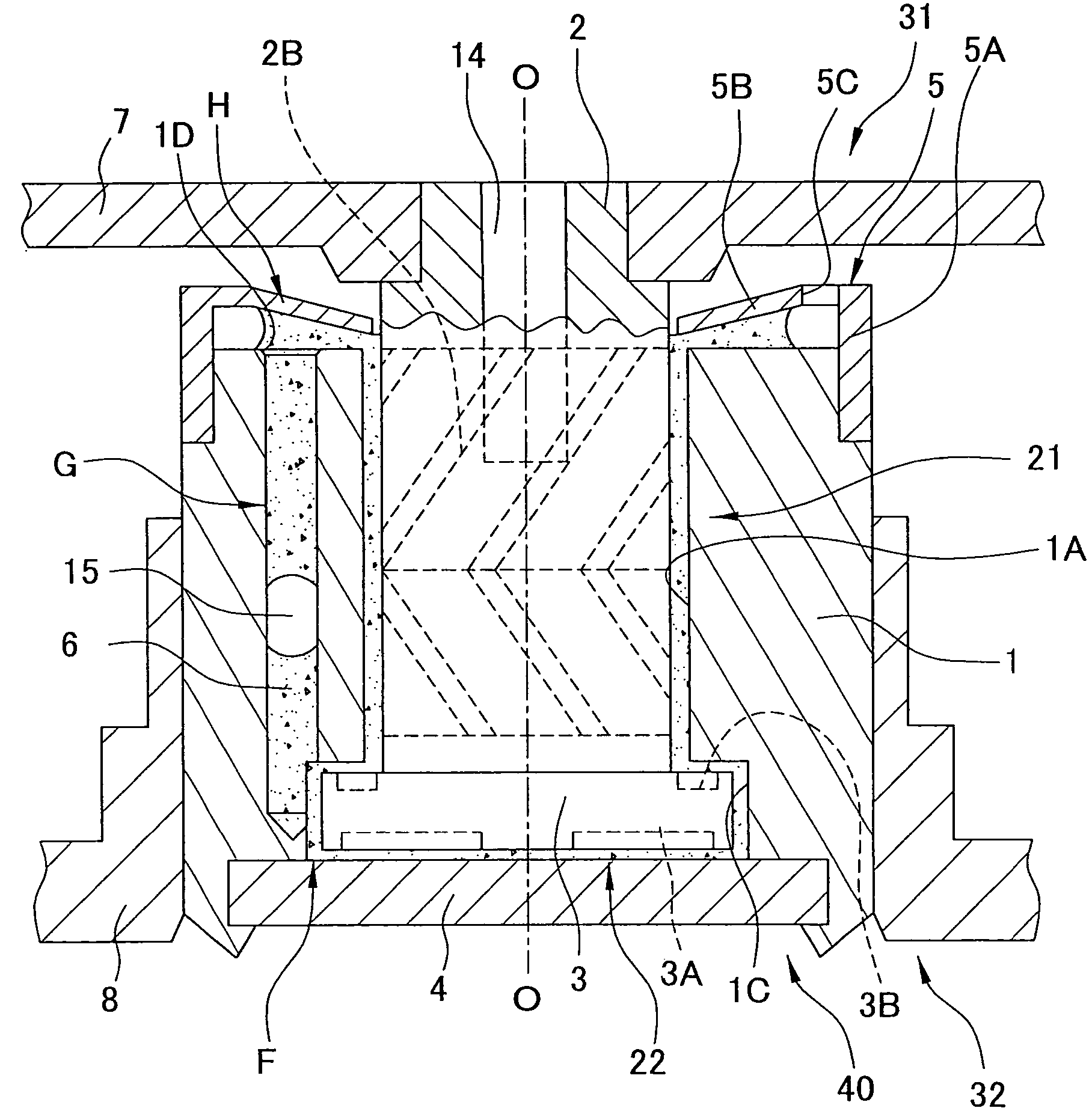
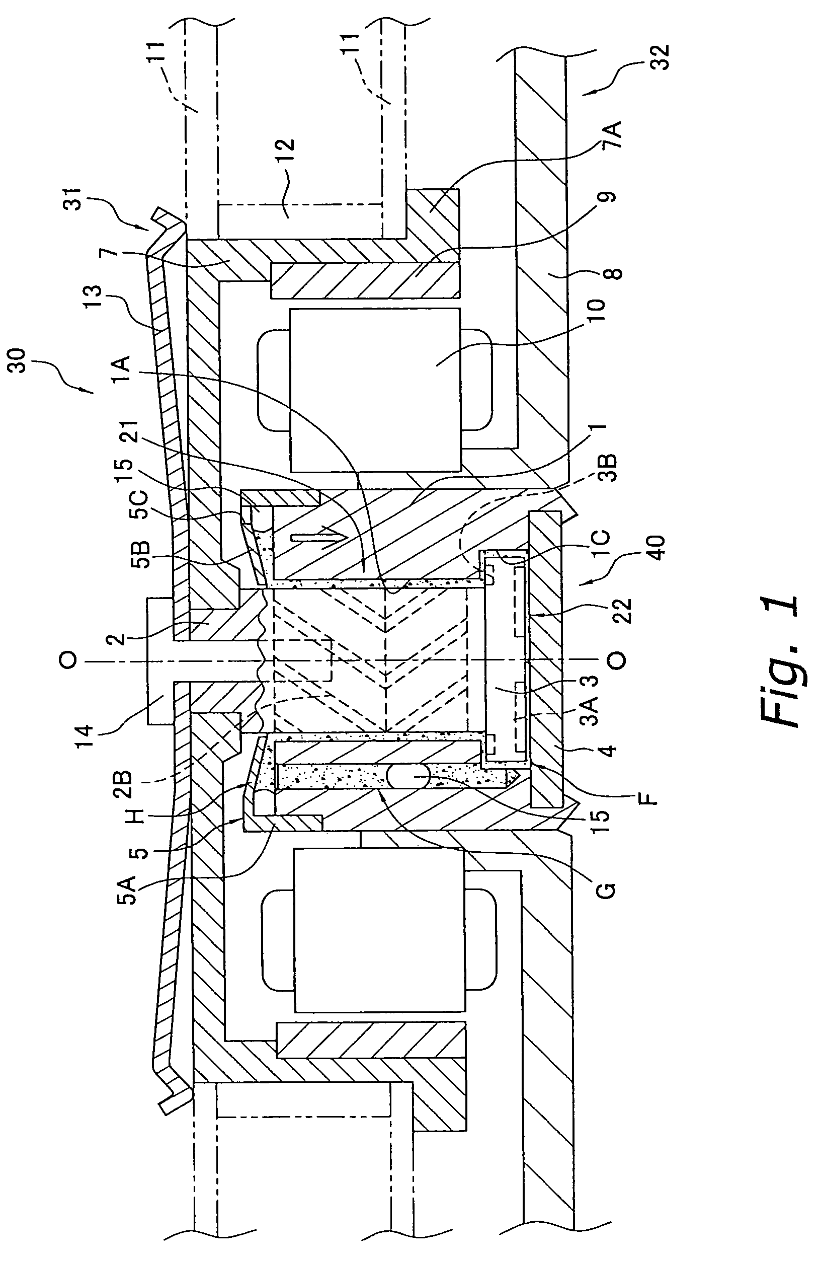
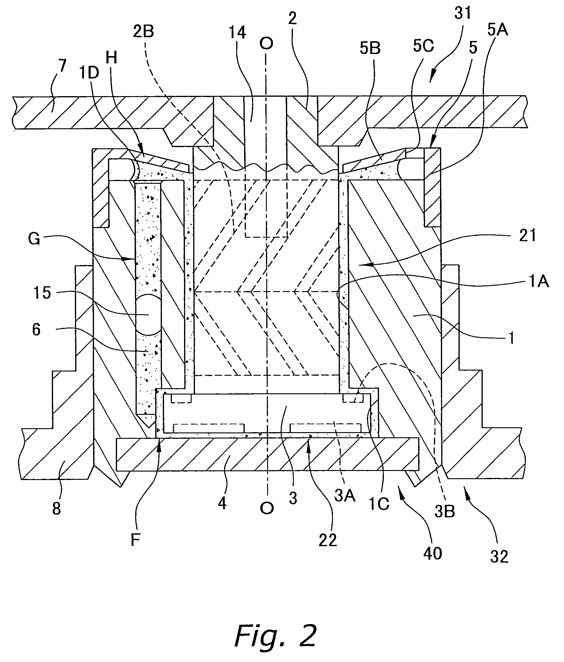
[0088]With reference to FIGS. 1 through 3, an example of a hydrodynamic bearing type rotary device 30 according to Embodiment 1 of the present invention will be described. Hereinafter, the vertical direction in FIG. 1 is referred to as “axial direction”, the upper side is referred to as “upper side in the axial direction” (one side in the axial direction), and the lower side is referred to as “lower side in the axial direction” (the other side in the axial direction). However, these expressions are not intended to limit how the actual hydrodynamic bearing type rotary device 30 is attached.

(1) Entire Structure of the Hydrodynamic Bearing Type Rotary Device 30

[0089]FIG. 1 is a schematic diagram of a vertical cross-section of the hydrodynamic bearing type rotary device 30 according to Embodiment 1 of the present invention. The hydrodynamic bearing type rotary device 30 is a device for driving rotation of a recording disc 11, and is mainly formed of a rotating member 31, a stationary me...

second embodiment

[0152]The principle of the capillary pressure as described above is also applicable to a hydrodynamic bearing type rotary device according to another embodiment. With reference to FIG. 14, a hydrodynamic bearing type rotary device 130 according to Embodiment 2 of the present invention will be described. FIG. 14 is a schematic diagram of a vertical cross section of the hydrodynamic bearing type rotary device 130 according to Embodiment 2 of the present invention. The hydrodynamic bearing type rotary device 130 according to Embodiment 2 has a so-called flangeless type hydrodynamic bearing mechanism 140. Hereinafter, a structure different from the hydrodynamic bearing type rotary device 30 according to Embodiment 1 will be mainly discussed.

[0153]As shown in FIG. 14, in the hydrodynamic bearing type rotary device 130, no flange is fixed to an end on the lower side in the axial direction of a shaft 102. On an outer peripheral surface of the shaft 102, radial dynamic pressure generating g...

third embodiment

[0167]The principle of the capillary pressure as described above is also applicable to a hydrodynamic bearing type rotary device which will be described below. With reference to FIG. 17, a hydrodynamic bearing type rotary device 230 according to Embodiment 3 of the present invention will be described. FIG. 17 is a schematic diagram showing a vertical cross-section of the hydrodynamic bearing type rotary device 230 according to Embodiment 3 of the present invention. Hereinafter, a structure different from the hydrodynamic bearing type rotary device 30 according to Embodiment 1 will be mainly discussed.

[0168]The hydrodynamic bearing type rotary device 230 includes a first sleeve 201, a second sleeve 217, a shaft 202, a flange 203, a cover plate 216 which serves as a thrust plate (or a closure plate), oil 206, and a hub 207.

[0169]On an outer periphery of the first sleeve 201, a communication groove 201C is formed. To an inner periphery of the second sleeve 217, the first sleeve 201 is ...


PUM


Abstract

A hydrodynamic bearing type rotary device which allows bubbles in a lubricating fluid to be surely discharged from a bearing portion is provided. A hydrodynamic bearing mechanism 40 of the hydrodynamic bearing type rotary device is formed of a sleeve 1, a shaft 2, a flange 3, a thrust plate 4, a seal cap 5, and oil 6. A first fluid reservoir F is formed between the sleeve 1, the flange 3, and the thrust plate 4. A second fluid reservoir H is formed between the sleeve 1 and the seal cap 5. In the sleeve 1, a communication hole G extending along an axial direction is formed. The first fluid reservoir F and the second fluid reservoir H communicate with each other through the communication hole G. The oil 6 is filled between the members. A capillary pressure is higher in the first fluid reservoir F than in the second fluid reservoir H.

Description

CROSS-REFERENCE TO RELATED APPLICATIONS[0001]This application claims priority to Japanese Patent Application Nos. JP2005-364050. The entire disclosures of Japanese Patent Application Nos. JP2005-364050 are hereby incorporated herein by reference.BACKGROUND OF THE INVENTION[0002]1. Field of the Invention[0003]The present invention relates to a hydrodynamic bearing type rotary device utilizing a hydrodynamic bearing mechanism and a recording and reproduction apparatus including the same.[0004]2. Background Information[0005]In recent years, hard disc apparatuses using recording discs experience an increase in a memory capacity and an increase in a transfer rate for data. Thus, hydrodynamic bearing type rotary devices suitable for high-speed rotation are used as driving apparatuses for such a type of recording apparatuses.[0006]The hydrodynamic bearing type rotary device mainly formed of, for example, a rotating member to which a recording disc is mounted, a stationary member attached t...

Claims


Application Information

Patent Timeline
Patent Type & Authority Patents(United States)
IPC IPC(8): F16C32/06
CPCF16C17/107F16C33/103F16C33/107F16C33/74F16C33/1085F16C33/745F16C2370/12
Inventor ASADA, TAKAFUMISAITO, HIROAKIITO, DAISUKE
Owner PHC HLDG CORP
Why Eureka
Try Eureka