Connector and receptacle containing a physical security feature

a technology of physical security and connectors, applied in the field of connectors, can solve the problems of optical connectors, high loss, couple, etc., and achieve the effects of low cost, low loss, and low cos

Inactive Publication Date: 2008-02-05
COMMSCOPE TECH LLC
View PDF6 Cites 167 Cited by
  • Summary
  • Abstract
  • Description
  • Claims
  • Application Information

AI Technical Summary

Benefits of technology

[0004]The present invention provides a connector system which uses physical barriers to prevent unauthorized users from connecting to data networks. More specifically, the applicants recognize that the best protection against unauthorized users “hacking” into data networks containing confidential information is to prevent them from even connecting to the network. This can be accomplished using physical barriers which prevent plugs from mating with receptacles. To this end, the present invention facilitates discriminating mating among similar, but different, plugs and receptacles by using a system of geometrically matched connector components which allows certain combinations of plugs and receptacles—i.e., mating pairs—to mate, while preventing other combinations from mating. Thus, the connector system of the present invention imparts physical security to a particular data network by ensuring that only authorized users who possess a particular connector component can physically connect to the particular data network.
[0006]Having the keying element located on the face of the plug provides for a number of benefits. First, these features can be molded with a relatively small change to the mold dies. Specifically, the opening around the ferrule is typically defined in the molding process by a core pin which is inserted into the outer mold. Changing core pin configurations is a relatively inexpensive and easy step compared to altering the configuration of the outer molds. Therefore, as mentioned above, the connector system of the present invention provides for a variety of different plug configurations with only slight modifications to the molding process.
[0007]Having the security features on the front face of the plug also provides for an early indication of non-mateability. Specifically, since the features are located on essentially the leading edge of the plug, they are positioned optimally to “stub” as soon as possible when a plug is inserted into a non-mating receptacle. The applicants recognize that interference between connector components which are non-mating should be made as soon as possible to minimize the possibility of coupling light between connectors. That is, if close enough, optical connectors are able to couple, albeit with high loss, even if the connectors are not mechanically engaged. This condition can be meliorated by preventing the light carrying elements from getting too close—hence the desire to stub early. Stubbing early also provides an early signal to the user that the plug is non-mating and avoids the tendency of trying to force a plug into a non-mating receptacle.
[0008]Additionally, by locating the keying feature on the leading surface of the plug, the corresponding keying feature on the receptacle may be located internally and still provide an early indication of non-mateability. This is beneficial since it is desirable to locate the keying feature of the receptacle internally to minimize the ability of the keying feature to be tampered with or otherwise overridden. As discussed below, this is of particular importance in the configuration of the MT-RJ and LC connectors in which the plug defines the slot and the receptacle defines the key. If the key is removed, the security feature is breached. Having the key located within the receptacle reduces this risk.
[0009]Yet another benefit of having the keying features located on the front face of the plug is the visual indication the plug provides with respect to its keying features. That is, one can readily determine the keying configuration of the plug by visual inspection of its front face. There is no need to look into an opening to inspect the internal geometry of the plug to determine its keying configuration.
[0010]Another aspect of the present invention is an economical process for producing the plugs by altering their geometry at their front end though a simple mold modification. In a preferred embodiment, the process comprises: (a) molding a first housing for a first plug of a set of plugs using a core pin to define an opening having a first keying element in a first position; and (b) molding a second housing for a second plug of the set of plugs by adjusting only the core pin to define the opening having a first keying element in a second position different than the first position.

Problems solved by technology

That is, if close enough, optical connectors are able to couple, albeit with high loss, even if the connectors are not mechanically engaged.

Method used


Image

  • Connector and receptacle containing a physical security feature
  • Connector and receptacle containing a physical security feature
  • Connector and receptacle containing a physical security feature

Examples


Embodiment Construction

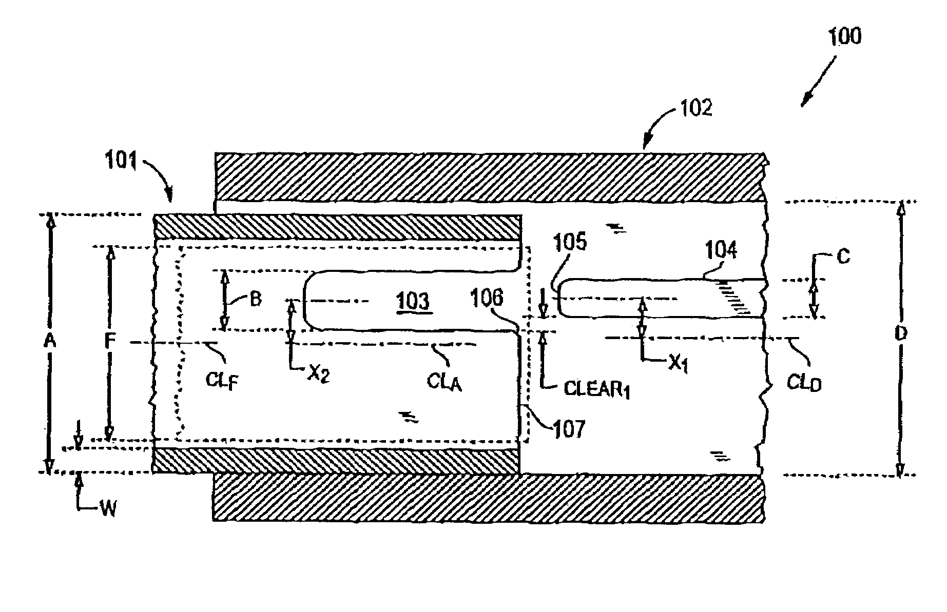
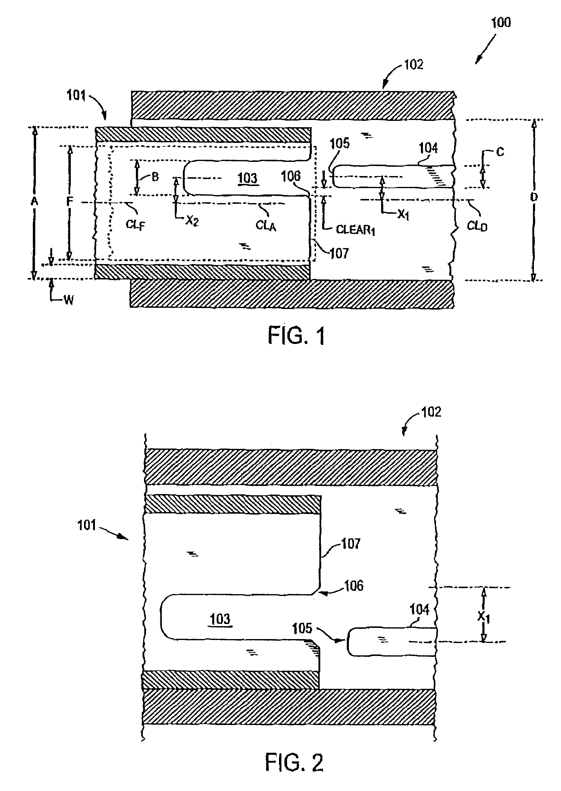
[0022]The present invention relates to a connector system comprising a series of connector components which interconnect with each other in a discretionary way. Referring to FIG. 1, a preferred embodiment of a mating plug 101 and receptacle 100 of the connector system is illustrated. As shown, the plug 101 is partially inserted into the receptacle 100, which, in this embodiment, is a jack having a tub portion 102. Although a jack is discussed herein in detail, it should be understood that the receptacle of the present invention is not restricted to a jack and may be any structure configured to receive a plug, including, for example, an adapter for connecting two plugs together or an integral connector on an active device (e.g., transceiver) or passive device (e.g., splitter).

[0023]The plug typically contains a conductive element, such a fiber or wire, which mates with a similar element in the receptacle. In fiber optic applications, it is common for the conductive element to be cont...


PUM


Abstract

A network comprising: (a) a plurality of different receptacles for facilitating an optical connection to different information networks requiring different access authorization, each different receptacle coupled to one and only one different information network, each receptacle having an inner surface with a first geometry, the first geometry comprising at least a slot, a certain number of receptacles having different first geometries in which the slots are in different positions; and (b) a plurality of different plugs for coupling with the different receptacles, each plug having a second geometry, the second geometry comprising at least a key in a certain position, the certain number of plugs having different second geometries in which the keys are in different positions, each different first geometry corresponding to one and only one second geometry such that the plugs and receptacles of corresponding first and second geometries are mating pairs.

Description

CROSS REFERENCE TO RELATED APPLICATIONS[0001]This application claims priority to U.S. Provisional Application No. 60 / 218,705, filed Jul. 17, 2000, U.S. application Ser. No. 09 / 908,140 filed Jul. 17, 2001, and U.S. application Ser. No. 10 / 982,374, filed Nov. 4, 2004, all of which are hereby incorporated by reference.FIELD OF INVENTION[0002]The present invention relates generally to connectors for use in telecommunication networks such as voice, data or video networks. More specifically, to a connector system in which only certain plugs can mate with certain receptacles to provide discriminating access to particular information networks.BACKGROUND[0003]A need has developed to limit user access in data networks for security or other purposes. In recent years, buildings / offices are being equipped with different information networks, each having access to different data. It is important to restrict access to these networks to only authorized users. While some restrictions may be achieved...

Claims


Application Information

Patent Timeline
Patent Type & Authority Patents(United States)
IPC IPC(8): G02B6/38
CPCG02B6/3831
Inventor GURRERI, MICHAEL L.ERDMAN, DAVID D.EDWARDS, BRYAN T.HOPKINS, ERIC J.BAECHTLE, DAVID R.
Owner COMMSCOPE TECH LLC
Why Eureka
Try Eureka