
Hair rendering method and apparatus

a hair and apparatus technology, applied in the field of computer animation, can solve the problems of hair not having a well-defined surface, process is not effective, hair has no shading process,

Inactive Publication Date: 2008-02-05
PIXAR ANIMATION
View PDF11 Cites 29 Cited by
  • Summary
  • Abstract
  • Description
  • Claims
  • Application Information

AI Technical Summary

Benefits of technology

The solution provides naturally appearing hair with coherent illumination between hair particles, reducing computational intensity and eliminating sparkling or popping effects, resulting in visually superior images.

Problems solved by technology

However, this process is not effective for shading hair, because hair is typically a large collection of infinitely thin curves (one-dimensional) that have little physical relation to neighboring hairs.
Further, this process is not effective because unlike standard surfaces, hair does not have a well-defined surface normal.
Drawbacks to tangent-based illumination solutions include that this method often leads to visually distracting artifacts.
Another drawback is that unrelated hairs that are spatially far apart may erroneously have the same lighting response.

Method used


Image

  • Hair rendering method and apparatus
  • Hair rendering method and apparatus
  • Hair rendering method and apparatus

Examples


Embodiment Construction

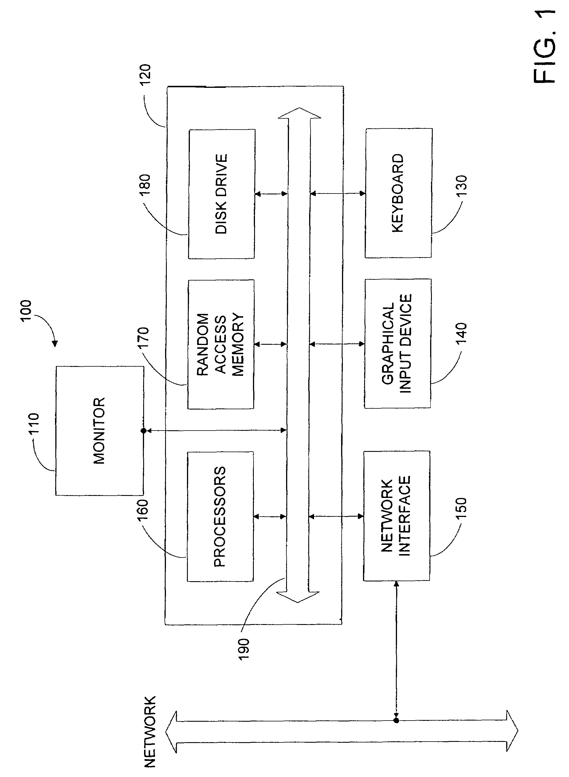
[0029]FIG. 1 is a block diagram of typical computer rendering system 100 according to an embodiment of the present invention.

[0030]In the present embodiment, computer system 100 typically includes a monitor 110, computer 120, a keyboard 130, a user input device 140, a network interface 150, and the like.

[0031]In the present embodiment, user input device 140 is typically embodied as a computer mouse, a trackball, a track pad, wireless remote, and the like. User input device 140 typically allows a user to select objects, icons, text and the like that appear on the monitor 110.

[0032]Embodiments of network interface 150 typically include an Ethernet card, a modem (telephone, satellite, cable, ISDN), (asynchronous) digital subscriber line (DSL) unit, and the like. Network interface 150 are typically coupled to a computer network as shown. In other embodiments, network interface 150 may be physically integrated on the motherboard of computer 120, may be a software program, such as soft DS...


PUM


Abstract

A method for rendering a plurality of geometrically thin objects in a computer system includes receiving a plurality of points associated with each of the plurality of geometrically thin objects, determining a plurality of volumetric point densities associated with the plurality of geometrically thin objects in response to the plurality of points, determining a plurality of volumetric point density gradients in response to the plurality of volumetric point densities, determining a plurality of surface normals associated with at least a subset of points in response to the plurality of volumetric point density gradients, and performing a rendering operation for the subset of points in response to the plurality of surface normals.

Description

CROSS-REFERENCES TO RELATED APPLICATIONS[0001]The present invention is a continuation of U.S. application Ser. No. 10 / 439,283 Filed May 14, 2003, now U.S. Pat. No. 7,098,910, and incorporates by reference for all purposes the following co-pending patent applications “Shot Rendering Method and Apparatus,” U.S. application Ser. No. 10 / 428,321 Filed Apr. 30, 2003 and “Method and Apparatus for Rendering of Translucent Objects Using Volumetric Grids,” U.S. application Ser. No. 10 / 428,322 Filed Apr. 30, 2003.BACKGROUND OF THE INVENTION[0002]The present invention relates to computer animation. More particularly, the present invention relates to techniques and apparatus for efficient rendering of hair on objects.[0003]Throughout the years, movie makers have often tried to tell stories involving make-believe creatures, far away places, and fantastic things. To do so, they have often relied on animation techniques to bring the make-believe to “life.” Two of the major paths in animation have t...

Claims


Application Information

Patent Timeline
Patent Type & Authority Patents(United States)
IPC IPC(8): G06T15/00G06FG06T13/00G06T15/50G06T15/60G06T15/70G06T17/00
CPCG06T13/40G06T15/50
Inventor PETROVIC, LENAANDERSON, JOHN R.
Owner PIXAR ANIMATION
Learn More