Method for determining a matrix of transmission cross coefficients in an optical proximity correction of mask layouts

a transmission cross coefficient and mask layout technology, applied in the field of determining the transmission cross coefficient matrix in the optical proximity correction of mask layout, can solve the problems of reducing the achievable resolution limit of the mask structure, inaccurate corrections of this type, distortion of the imaged mask layout on the semiconductor substrate wafer, etc., and achieves the effect of fast and efficient establishmen

Inactive Publication Date: 2008-02-05
POLARIS INNOVATIONS LTD
View PDF4 Cites 5 Cited by
  • Summary
  • Abstract
  • Description
  • Claims
  • Application Information

AI Technical Summary

Benefits of technology

[0010]The present invention provides an improved method for an optical modeling in an optical proximity correction, an improved optical proximity correction and a mask layout created with the aid of an optical proximity correction in the case of which a matrix of transmission cross coefficients is determined significantly more rapidly and more efficiently.
[0012]In one aspect according to the invention, the invention is based on the application of the convolution theorem of Fourier transformation to the above-described integral for determining the matrix of transmission cross coefficients. Compared with the direct naïve evaluation of the integral, the invention's calculation in the Fourier space proves to be significantly faster and more efficient, particularly for the case of very large image matrices of the illumination aperture, the lens aperture and the complex conjugate lens aperture. Consequently, the method according to the invention makes it possible to use image matrices with a fine raster and thus to form a precise optical model which reproduces the underlying properties of the lens system or the illumination settings precisely and realistically.
[0015]One advantage of the calculation in the Fourier space becomes evident from the comparison of the two formulae. The multiple evaluation of the abovementioned integral that is carried out for a multiplicity of different displacement vectors is extremely complicated, particularly given the presence of image matrices with a fine raster, i.e. a large number of matrix elements. The calculation of the transmission cross coefficients by Fourier transformation of the illumination aperture, the lens aperture and the complex conjugate lens aperture, multiple multiplication of the Fourier transforms of the individual apertures given corresponding displacement frequencies and subsequent inverse transformation is significantly faster, by contrast.
[0020]The optical proximity correction according to the invention is correspondingly distinguished by a very fast and efficient establishment of the matrix of the transmission cross coefficients for the optical modeling, as a result of which a corrected mask layout of a lithography mask can be provided more rapidly. Furthermore, the use of very precise apertures which therefore reproduce well the illumination settings and the optical properties of a lens system is made possible. The optical proximity correction becomes very precise and exact in this way.
[0021]In still another embodiment of the invention, there is a mask layout for a lithography mask with a mask structure which contains the optical proximity correction described above. A mask layout of a lithography mask corrected in this way enables undesirable imaging distortions to be compensated for very efficiently.

Problems solved by technology

However, optical errors and process errors give rise to distortions of the imaged mask layout on the semiconductor substrate wafer.
Distortions of this type, which occur especially in the case of very small mask structures having structure sizes smaller than the wavelengths of the electromagnetic radiation used, consequently reduce the achievable resolution limit of the mask structures.
However, one disadvantage is that corrections of this type are inaccurate particularly in the case of very small structures and, as a result, imaging distortions may possibly be compensated for only inadequately.
However, if the apertures are given as “bitmaps” or image matrices which enable a more complex and precise description of the underlying lens system and the illumination settings, then the evaluation takes substantially longer depending on the desired accuracy or the size of the raster of the image matrices.
Consequently, an optical modeling carried out with a high accuracy requires a very high expenditure of time.
This expenditure of time can only be reduced by reducing the accuracy of the modeling and thus of the later correction run.

Method used


Image

  • Method for determining a matrix of transmission cross coefficients in an optical proximity correction of mask layouts
  • Method for determining a matrix of transmission cross coefficients in an optical proximity correction of mask layouts
  • Method for determining a matrix of transmission cross coefficients in an optical proximity correction of mask layouts

Examples


Embodiment Construction

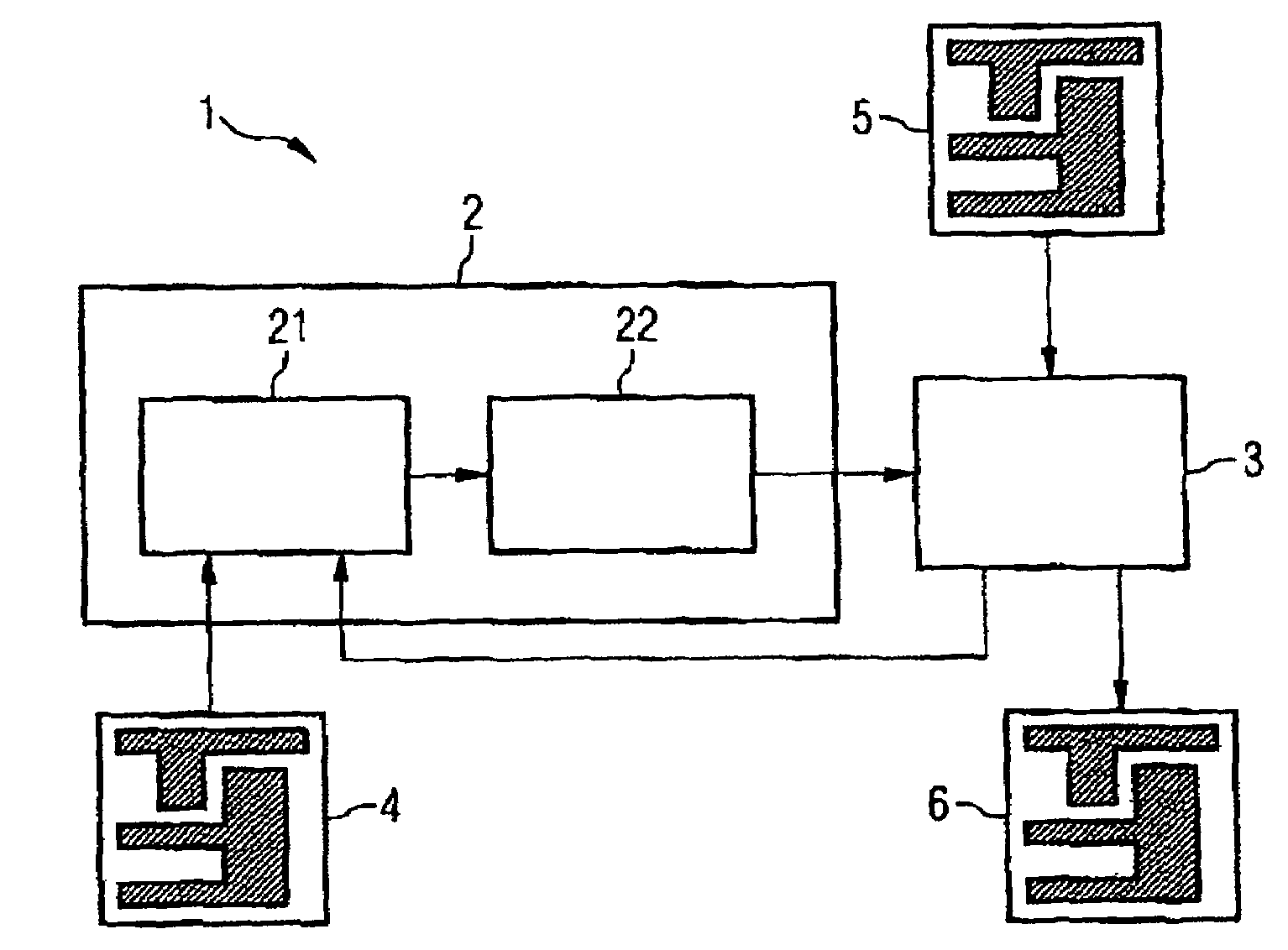
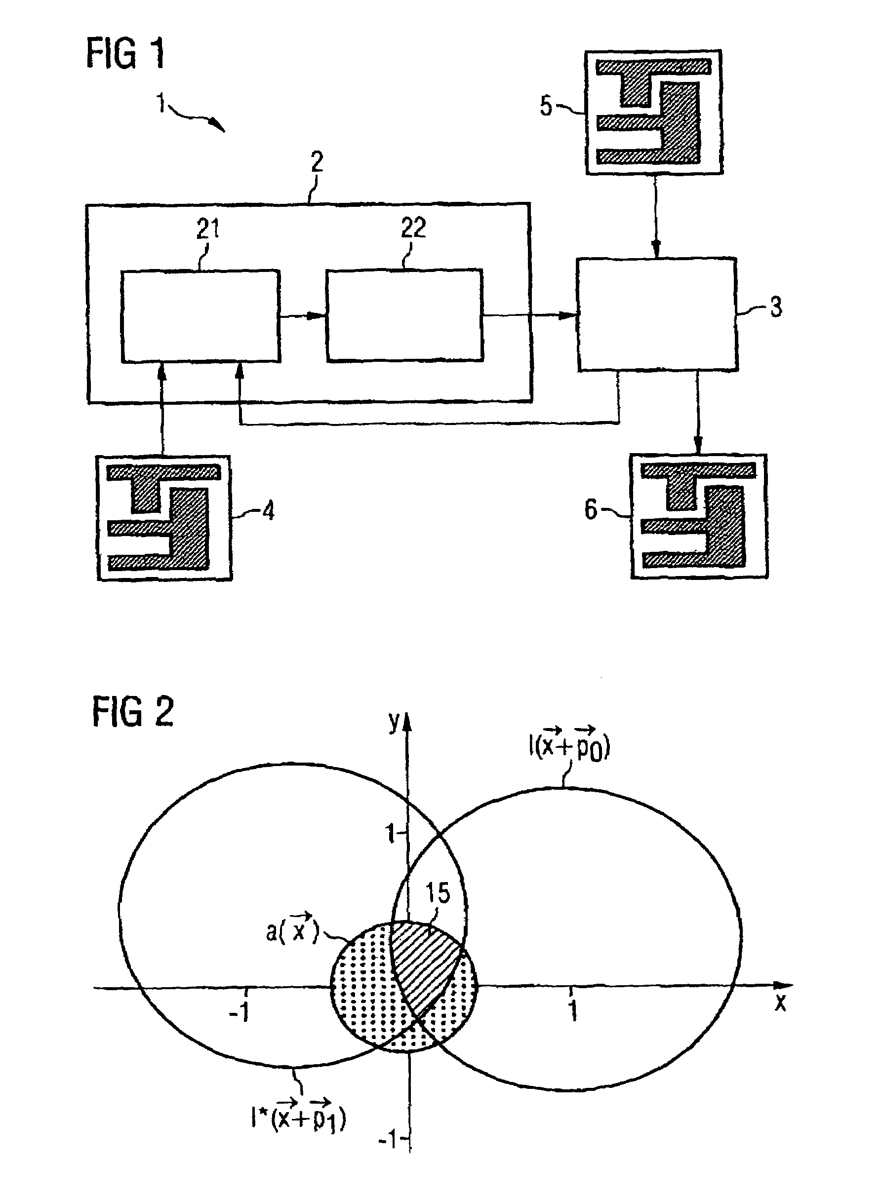
[0028]FIG. 1 shows a block diagram of a typical correction run 1 of a model-based optical proximity correction for a mask structure of an original mask layout 4 of a lithography mask. With the aid of the correction run 1 carried out on a computer, corrections are made to the mask layout 4, which largely compensate for distortions of the image of the mask layout 4 on a semiconductor substrate wafer that occur during a lithography process.

[0029]For this purpose, firstly a simulation of the image of the mask structure of the original mask layout 4 is carried out with the aid of a simulation unit 2. The simulation unit 2 has an optical model 21 and also a resist model 22.

[0030]The optical model 21 is used to register illumination settings of the radiation source used for a lithography process, for example the geometry of an illumination diaphragm and an illumination angle, and also imaging properties of a lens or a lens system used for imaging the mask layout 4 onto a photoresist layer ...


PUM

PropertyMeasurementUnit
transmission cross coefficientsaaaaaaaaaa
optical modelaaaaaaaaaa
displacement frequenciesaaaaaaaaaa

Abstract

The present invention relates to a method for determining a matrix of transmission cross coefficients w for an optical modeling in an optical proximity correction of mask layouts. In a first step, there is calculation of Fourier transforms of an illumination aperture, a lens aperture and a complex conjugate lens aperture, which are present in the form of image matrices with a predetermined raster. A second step involves calculating Fourier transforms for the transmission cross coefficients w from the Fourier transforms by means of a convolution theorem in order to obtain the matrix of the Fourier transforms of the transmission cross coefficients w. A further step involves inverse-transforming the Fourier transforms of the transmission cross coefficients w by means of a fast Fourier transformation in order to obtain the matrix of the transmission cross coefficients w for the optical modeling in the optical proximity correction of mass layouts.

Description

CLAIM FOR PRIORITY[0001]This application claims the benefit of priority to German Application No. 10 2004 030 961.2, filed Jun. 26, 2004, the contents of which are hereby incorporated by reference.TECHNICAL FIELD OF THE INVENTION[0002]The present invention relates to a method for determining a matrix of transmission cross coefficients for an optical modeling in an optical proximity correction of mask layouts, and to an optical proximity correction for a mask structure of a mask layout and also to a mask layout for a lithography mask with a mask structure.BACKGROUND OF THE INVENTION[0003]Particular patterning methods are used for fabricating large scale integrated electrical circuits with small structure dimensions. One of the most familiar methods known since the beginnings of semiconductor technology is the lithographic patterning method. In this case a radiation-sensitive resist or photoresist layer is applied to the surface of a semiconductor substrate wafer to be patterned and i...

Claims


Application Information

Patent Timeline
Patent Type & Authority Patents(United States)
IPC IPC(8): G06F17/50G06F17/10G03F1/00G03F1/36
CPCG03F1/144G03F1/36G03F7/70441G03F7/705
Inventor KOHLE, RODERICK
Owner POLARIS INNOVATIONS LTD
Why Eureka
Try Eureka