
Display rack transport device

a technology for transporting which is applied in the direction of hand cart accessories, domestic applications, applications, etc., can solve the problems of damage to display racks and/or products and goods stored, damage to the floor surface, and difficulty in moving or repositioning display racks, etc., to achieve efficient and safe, increase the flexibility and capability of transport devices and display racks

Active Publication Date: 2008-02-12
FIXTURE TECH
View PDF44 Cites 45 Cited by
  • Summary
  • Abstract
  • Description
  • Claims
  • Application Information

AI Technical Summary

Benefits of technology

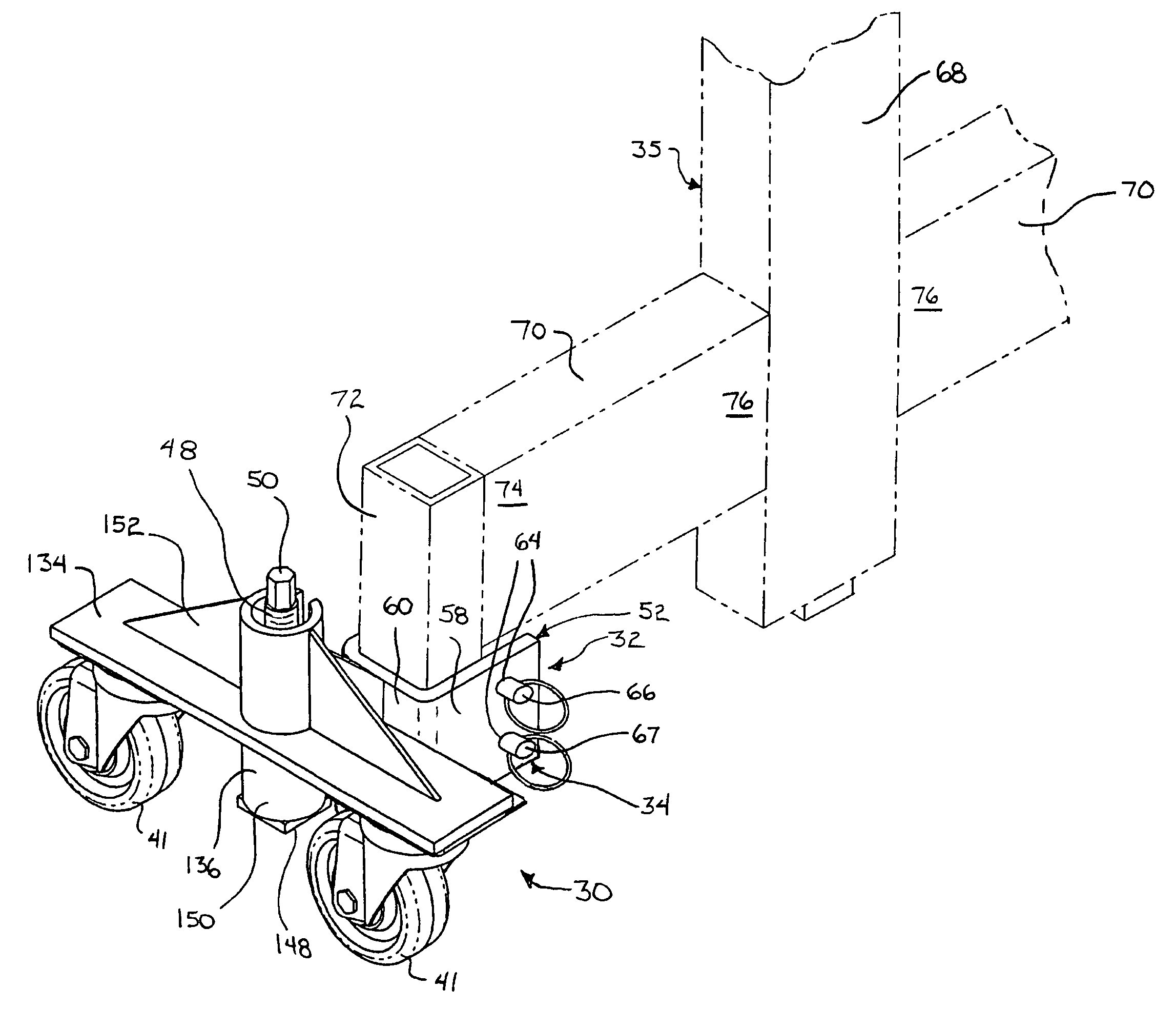
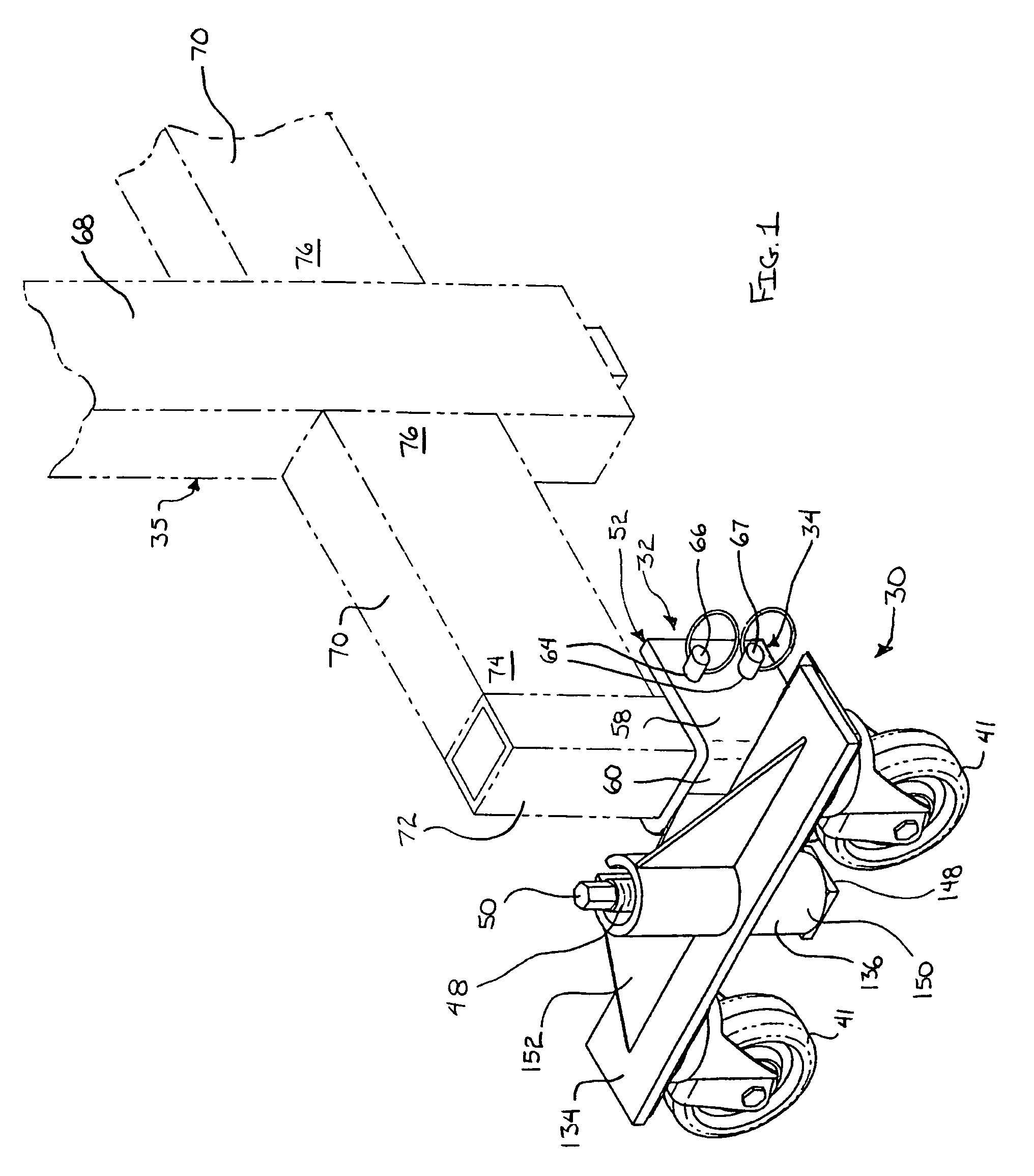
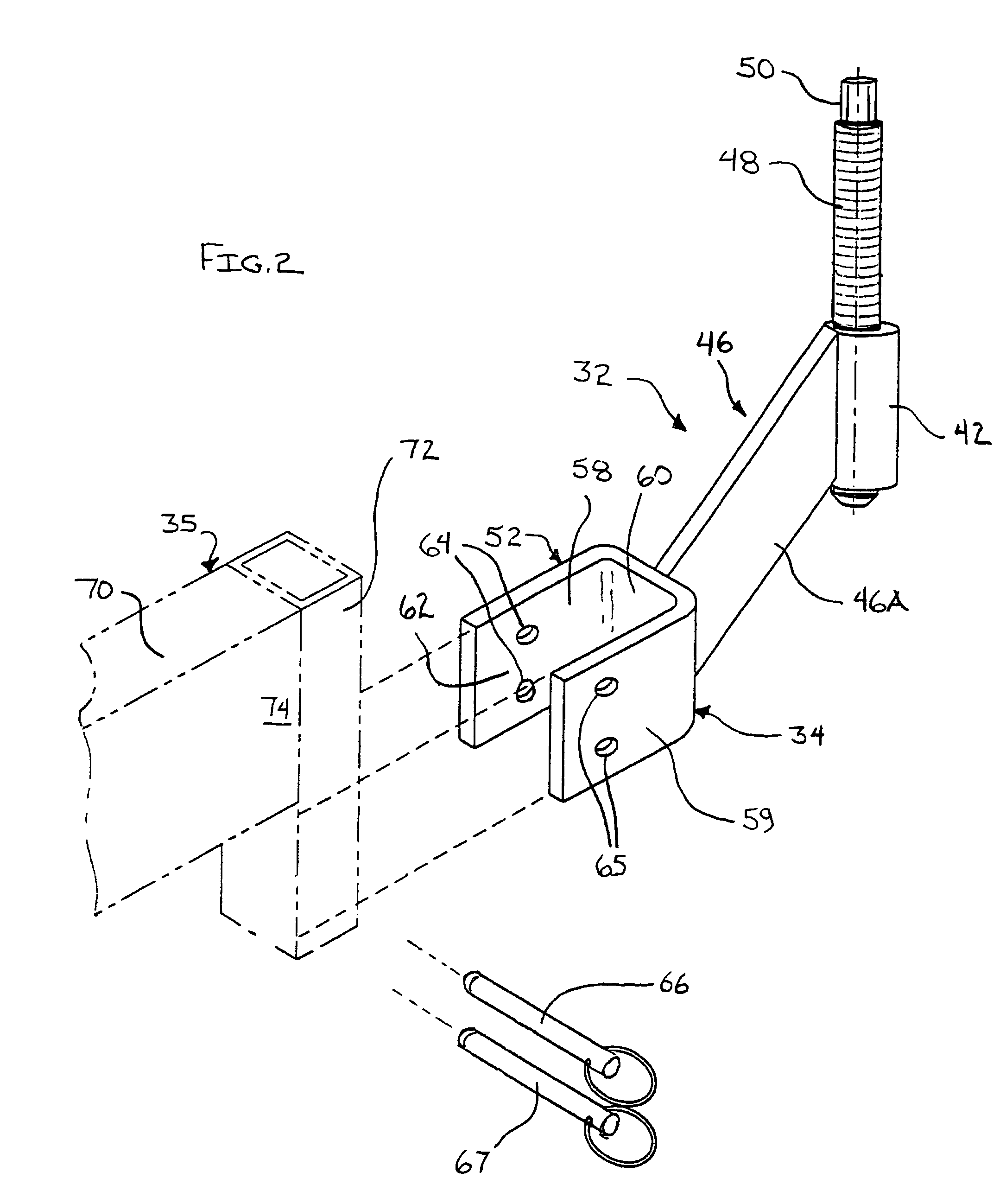
[0011]The display rack transport device of the present invention provides an efficient and safe method for relocating display racks, such as pallet racks, storage racks, shelf racks, and / or the like. A common wheel assembly may be used with multiple different display mounts, such as a pallet rack mount, storage rack mount, shelf rack mount, and / or the like, thereby enabling many different display racks to be moved using fewer components. In addition, the ability of the pallet rack mount and the storage rack mount to affix to different models or styles of pallet racks and storage racks, respectively, further increases the flexibility and capability of the transport device. By securing multiple display mounts located within wheel assemblies to a display rack, the display rack may be raised in an accurate and controlled manner, such as by rotation of a threaded rod. Upon elevating the display rack, it may be easily and efficiently relocated by the wheeled transport devices, and subsequently lowered at the relocated area, such as by rotating the threaded rod in the opposite direction.

Problems solved by technology

This moving or repositioning of display racks can be difficult and time consuming.
In addition to being time consuming, such a process may also cause damage to the display racks and / or the products and goods stored on the display racks due to the additional handling.
However, this method is also problematic in that damage may occur to the floor surface or injuries may result.

Method used


Image

  • Display rack transport device
  • Display rack transport device
  • Display rack transport device

Examples


Embodiment Construction

[0024]The present invention is embodied in a display rack transport device for the moving or re-positioning of display racks. The display rack transport device of the present invention may enable several different styles of display racks to be readily moved using a minimum or reduced number of different components and effort.

[0025]Two embodiments of the present invention can be seen in FIGS. 1 and 5 as comprising a wheel assembly 30 and a display mount 32, 132 where the display mounts 32, 132 are removable from the wheel assembly 30 and are adapted to engage different styles of display racks. The first display mount 32 of FIG. 1 is a shelf rack mount 34 adapted to mate with a support stand 35 of a shelf rack that is constructed of multiple support stands 35 connected by multiple horizontal shelves (not shown). The second display mount 132 of FIG. 5 is a pallet rack mount 36 adapted to mate to the generally vertical member or pallet rack leg 37 of a pallet rack that stores pallets of...


PUM


Abstract

A display rack transport device includes a wheel assembly and a display mount. The display mount is removably mountable to the wheel assembly and mountable to a display rack. Variously configured display mounts are adapted to mount to various styles of display racks, such as pallet racks, storage racks, and shelf racks. The wheel assembly includes one or more pivotally mounted wheels and is adapted to enable the display mount to raise and lower relative to the wheel assembly when the display mount is mounted to the wheel assembly. The raising and lowering of a display mount that is mounted to a display rack enables the display rack to be repositioned utilizing the pivoting wheels of the wheel assembly.

Description

CROSS REFERENCE TO RELATED APPLICATION[0001]The present application claims priority of U.S. provisional application, Ser. No. 60 / 555,490, filed Mar. 23, 2004, by Bileth for DISPLAY RACK TRANSPORT DEVICE, which is hereby incorporated herein by reference in its entirety.BACKGROUND AND TECHNICAL FIELD OF THE INVENTION[0002]The present invention is directed to a display rack transport device for the moving of display and storage racks, and in particular a preferred embodiment of the present invention enables multiple styles of display racks to be easily moved using a limited number of components.[0003]Display racks are commonly used to store or exhibit products and typically have multiple horizontal shelves, or storage locations, such that a greater quantity of goods may be stored or displayed within a given area. Display racks are commonly seen in grocer stores, general merchandise stores, and clothing stores. However, many variations of display racks exist and are utilized in other en...

Claims


Application Information

Patent Timeline
Patent Type & Authority Patents(United States)
IPC IPC(8): B62B1/04
CPCA47F5/137B62B5/0083B62B5/0086
Inventor BILETH, JACK L
Owner FIXTURE TECH
Learn More