
Regenerative control apparatus for vehicles equipped with a lock-up clutch

a technology of regenerative control apparatus and lock-up clutch, which is applied in the direction of hybrid vehicles, engine-driven generators, transportation and packaging, etc., can solve the problems of engine stall, engine speed may drastically decrease, engine-generated torque may be decreased, etc., to increase the energy regeneration rate, prevent the occurrence of engine stall, and increase the regenerative generation rate

Active Publication Date: 2008-02-12
DENSO CORP
View PDF11 Cites 15 Cited by
  • Summary
  • Abstract
  • Description
  • Claims
  • Application Information

AI Technical Summary

Benefits of technology

[0013]The present invention has been made in view of the problems described above, and has as its object to provide a regenerative control apparatus for vehicles equipped with a lock-up clutch, which enhances the efficiency of recovering regenerative braking energy, while suppressing engine stall due to drastic increase of engine load torque.

Problems solved by technology

However, the regenerative braking control as disclosed in Japanese Unexamined Patent Application Publication No. 07-310566, and the mode for performing regenerative braking after bringing a lock-up clutch into a complete engagement state as disclosed in Japanese Unexamined Patent Application Publication No. 2004-224110, have arisen such disadvantages as provided below.
In particular, in both of the cases, although good regenerative braking may be performed in a high-speed range of a vehicle, if some causes for drastically increasing engine load torque are given (e.g., a case where a hard stop is made in the complete engagement state of a lock-up clutch to lock the wheels), the engine speed may drastically decrease.
Accordingly, the engine-generated torque may be decreased, possibly falling into a state of engine stall.
In particular, in these cases, although the engine stall described above is unlikely to be caused, there may be a problematic large energy loss in an automatic transmission and thus sufficient regeneration may not be expected.
Further, as a result of drastic decrease of the engine speed due to regenerative braking, which necessitates stoppage of fuel cutting to prevent engine stall, fuel consumption may tend to be deteriorated.
In return, however, the risk of engine stall may be increased.
If, on the contrary, regenerative control is performed in a state where coupling of a lock-up clutch has been weakened, the risk of engine stall may be decreased.
In this case, however, because the automatic transmission (typically, its hydraulic torque converter) is not being locked up, regenerative energy may not be effectively recovered.
As a result, when regenerative generation is forcedly performed, the engine speed may tend to be drastically decreased to cause engine stall.

Method used


Image

  • Regenerative control apparatus for vehicles equipped with a lock-up clutch
  • Regenerative control apparatus for vehicles equipped with a lock-up clutch
  • Regenerative control apparatus for vehicles equipped with a lock-up clutch

Examples


Embodiment Construction

[0036]The preferred aspects of the present invention will now be described in detail by way of an embodiment provided below. Note that the present invention should not be limited to the following embodiment, but the concept of the present invention may be realized using other known techniques.

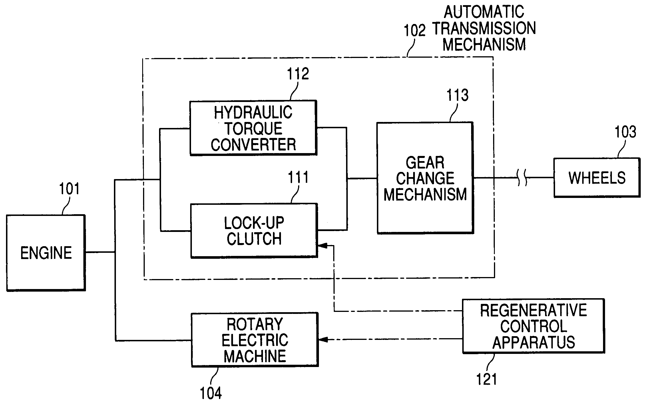
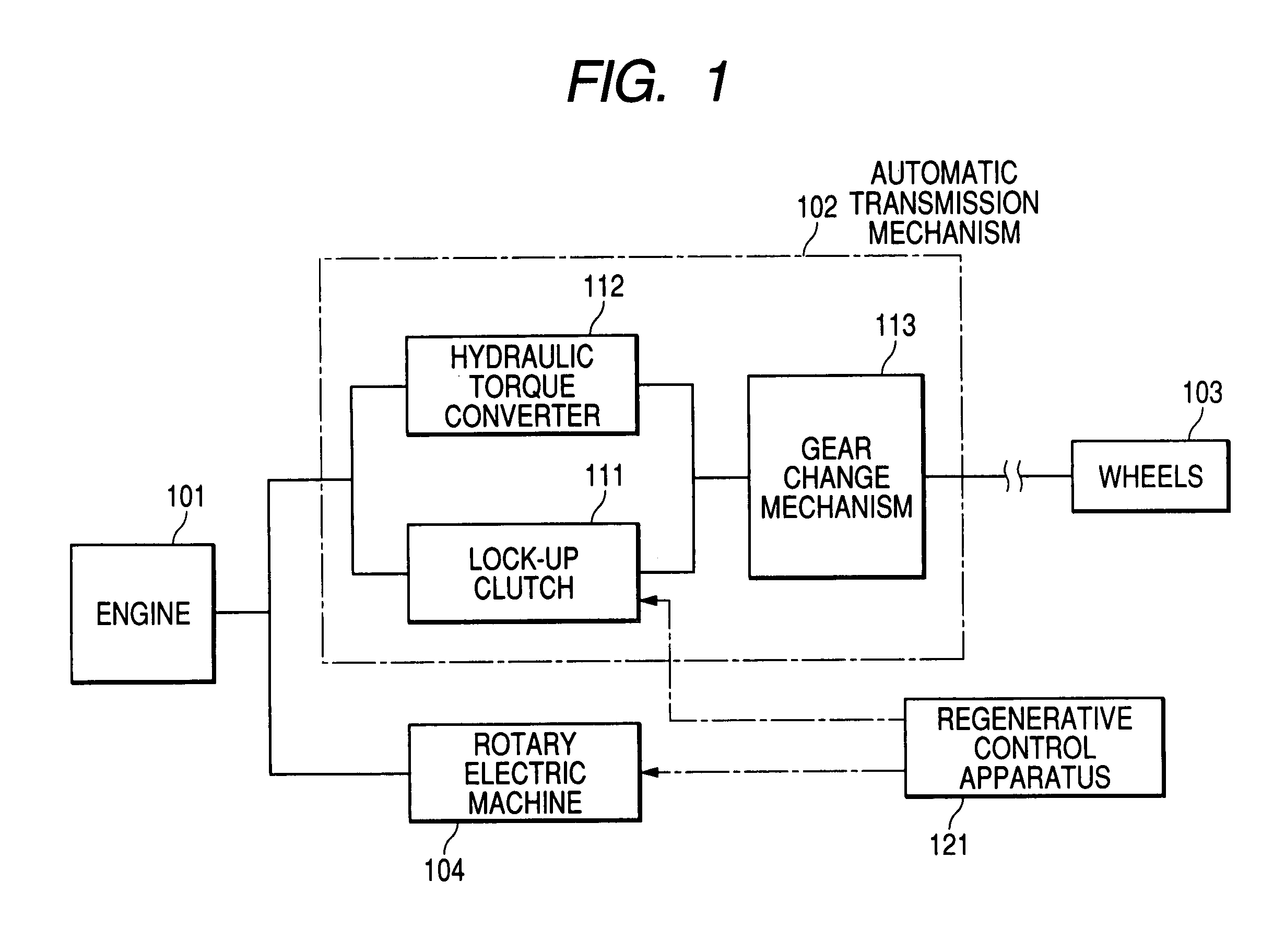
[0037]With reference to FIG. 1, a brief explanation will now be given hereunder on a power transmission system for vehicles equipped with a lock-up clutch loaded with a regenerative control apparatus related to this embodiment.

[0038]In such a vehicle equipped with a lock-up clutch, an engine 101 transmits power to wheels 103 through an automatic transmission (automatic transmission mechanism AT) 102. The engine 101 is linked to a rotary electric machine 104 in a manner enabling torque reception / transmission. The rotary electric machine 104 substantially carries out regenerative generation with the aid of energy from the engine at the time of decelerating the vehicle. The rotary electric machine...


PUM


Abstract

For regenerative generation at deceleration of a vehicle, a regenerative control apparatus for vehicles equipped with a lock-up clutch comprises a control unit for controlling rotary electric machine and the lock-up clutch. When the clutch is in a complete disengagement state or a slipping state at deceleration, the control unit controls the rotary electric machine to execute regenerative generation at a partial generation level lower than a regenerative generation level in a complete engagement state. When the clutch is in a complete engagement state at regenerative generation, the control unit controls the clutch so that the coupling state is transferred to a slipping state or a complete disengagement state when the number of revolutions having correlation to engine speed becomes lower than a predetermined threshold. Thus, recovering efficiency of the regenerative braking energy can be enhanced, while suppressing engine stall due to drastic increase of engine load torque.

Description

CROSS-REFERENCE TO RELATED APPLICATION[0001]This application is based on and claims the benefit of priority from earlier Japanese Patent Application No. 2004-380046 filed on Dec. 28, 2004, the description of which is incorporated herein by reference.BACKGROUND OF THE INVENTION[0002]1. Technical Field of the Invention[0003]The present invention relates to a regenerative control apparatus for vehicles equipped with a lock-up clutch for complete engagement with a hydraulic torque converter.[0004]2. Prior Art[0005]Regenerative control apparatuses for use in vehicles equipped with a lock-up clutch have been suggested.[0006]Japanese Unexamined Patent Application Publication No. 07-310566, for example, suggests starting regenerative braking after bringing a lock-up clutch into a state of complete engagement, and stopping the regenerative braking after bringing the lock-up clutch into a state of complete disengagement when an engine speed becomes lower than a fuel-cut releasing speed.[0007]...

Claims


Application Information

Patent Timeline
Patent Type & Authority Patents(United States)
IPC IPC(8): B60W10/02B60L50/16
CPCB60W10/02B60W10/026B60W10/08B60W10/11F16H61/143B60W30/18127Y10T477/27Y10T477/26Y10T477/78B60L7/10
Inventor SENDA, TAKASHIISOBE, DAIJI
Owner DENSO CORP
Learn More