
Medical treatment instrument

a technology for treating instruments and instruments, applied in the field of medical treatment instruments, can solve the problems of insufficient compression of inability to thermally coagulate patient's body tissue such as blood vessels, and the portion of scissors section at the rear end of the grasp portion cannot be made of metal, so as to reduce the degradation of the dissection capability of a dissection portion and maintain the sharpness of the dissection portion

Inactive Publication Date: 2008-02-12
OLYMPUS CORP
View PDF49 Cites 688 Cited by
  • Summary
  • Abstract
  • Description
  • Claims
  • Application Information

AI Technical Summary

Benefits of technology

[0008]The present invention has been achieved in view of the foregoing circumference. It is an object of the present invention to provide a medical treatment instrument capable of reliably thermally coagulating a patient's body tissue such as blood vessel grasped between a pair of treatment members and capable of reducing degradation of the dissection capability of a dissection portion due to a scissors during in use and maintaining sharpness of the dissection portion for a long period of time.
[0015]Therefore, according to the present invention, the heat generating portion to be current-carried and heated is provided at least at one grasp portion on the tip side of the treatment portion; the patient's body tissue grasped between a pair of the grasp portions is coagulated by heat of the heat generating portion, and the cutting portion with the scissors and cutting the patient's body tissue on the rear side of the grasp portions is provided. Thus, the patient's body tissue such as blood vessel grasped between a pair of the grasp portions can be reliably thermally coagulated by heat of the heat generating portion. Further, degradation of the cutting capability of the cutting portion due to the scissors during in use is reduced, and the sharpness of the cutting portion can be maintained for a long period of time.

Problems solved by technology

As a result, there is a problem that the patient's body tissue such as blood vessel cannot be sufficiently compressed between the two scissor constituent members, and the patient's body tissue such as blood vessel cannot be thermally coagulated.
In addition, the treatment instrument disclosed in U.S. Pat. No. 5,342,381 is configured to supply a bipolar high-frequency current to the grasp portion at the tip side of the treatment section, so that a portion of the scissors section at the rear end of the grasp portion cannot be made of metal.
However, thus, there is a problem that, when a ceramic based scissors portion is used, the dissection capability is gradually degraded due to a friction between slide portions of the scissors portion during in use.

Method used


Image

  • Medical treatment instrument
  • Medical treatment instrument
  • Medical treatment instrument

Examples


first embodiment

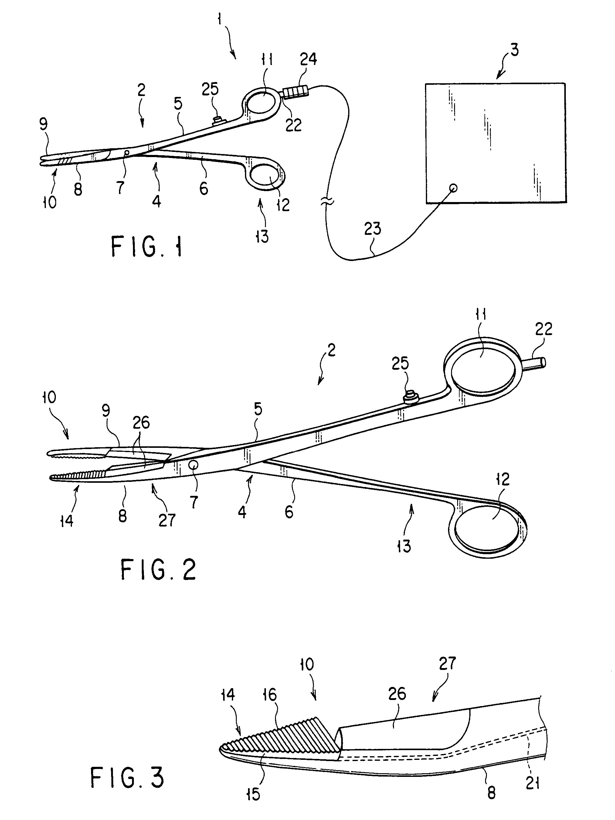
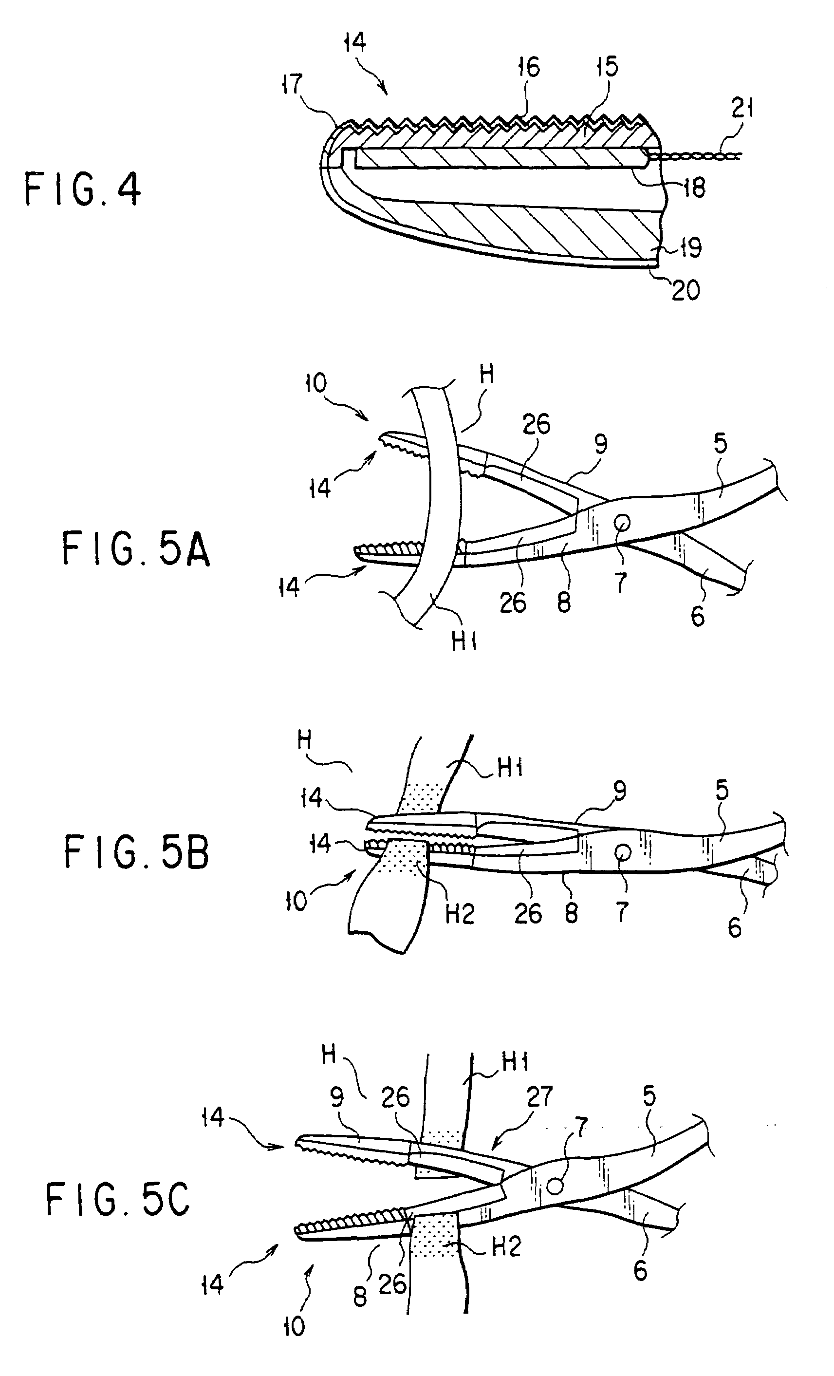
[0181]Hereinafter, the present invention will be described with reference to FIGS. 1 to 5C. FIG. 1 shows a schematic configuration of the entire system of a medical treatment instrument 1 according to the present embodiment. The medical treatment instrument 1 of the present embodiment is provided with a pair of scissor forceps 2 and a generator 3 connected to this scissor forceps 2.

[0182]Here, a forceps main body (treatment instrument main body) 4 of the scissor forceps 2 is provided with two scissor constituent members 5 and 6 as shown in FIG. 2. These scissor constituent members 5 and 6 are placed so that their intermediate portions substantially cross with each other. Further, a support shaft 7 rotatably linking the scissor constituent members 5 and 6 with each other is arranged at a cross section of both of these scissor constituent members 5 and 6.

[0183]In addition, a treatment portion 10 comprising a pair of opening / closing elements 8 and 9 capable of being opened or closed is...

fourth embodiment

[0217]FIGS. 9A and 9B show the present invention. FIG. 9A shows a schematic structure of the entire surgical treatment instrument 51 used for surgical operation under endoscope that is a medical treatment instrument of the present embodiment. A treatment instrument 51 of the present embodiment is provided with an elongated insert portion 52 to be inserted into the patient body through trocar (not shown); and a frontal operating portion 53 coupled with the proximal end of this insert portion 52.

[0218]In addition, the insert portion 52 is provided with a tubular insert tube body 54. A driving shaft 55 relatively driven in axial direction of the insert portion 52 is inserted into this insert tube body 54. Further, a treatment portion 56 is arranged at the tip of the insert portion 52. This treatment portion 56 is provided with a pair of grasp members (opening / closing elements) 57a and 57b capable of being opened and closed. Here, a pair of the grasp members 57a and 57b is coupled with ...

seventh embodiment

[0238]FIGS. 12 and 13 show the present invention. FIG. 12 shows a schematic structure of the entire system of a medical treatment instrument 101 according to the present embodiment. The system of the medical treatment instrument 101 according to the present embodiment is provided with a forceps 102 and a power supply unit 103 connected to this forceps 102.

[0239]A main body 104 of the forceps 102 is provided with two scissor constituent members 105 and 106. These scissor constituent members 105 and 106 are placed in a state in which the intermediate portions substantially cross with each other. Further, a support shaft 107 is arranged at the cross section of these scissor constituent members 105 and 106 to rotatably link the scissor constituent members 105 and 106.

[0240]In addition, a treatment portion 110 comprising a pair of grasp portions 108 and 109 capable of being opened and closed, which grasps the patient's body tissue, is arranged at the tip of the forceps main body 104. Thi...


PUM


Abstract

According to the present invention, a heat generating element to be current-carried is provided at a grasp portion on the tip side of a treatment portion, the patient's body tissue grasped between a pair of grasp portions is coagulated by heat of the heat generating element, and a metal scissors blade for cutting the patient's body tissue is provided on the rear side of the grasp portion in the treatment portion.

Description

CROSS-REFERENCE TO RELATED APPLICATIONS[0001]This is a continuation of U.S. patent application Ser. No. 09 / 793,431, filed Feb. 26, 2001, which is abandoned, which is a continuation-in-part of U.S. patent application Ser. No. 09 / 488,732, filed Jan. 20, 2000, which is abandoned, the entire contents of each of which are incorporated herein by reference.[0002]This application is based upon and claims the benefit of priority from the prior Japanese Patent Applications Nos. 11-015661, filed Jan. 25, 1999; No. 2000-327148, filed Oct. 26, 2000; and No. 2000-164905, filed Jun. 1, 2000, the entire contents of each of which are incorporated herein by reference.BACKGROUND OF THE INVENTION[0003]The present invention relates to a medical treatment instrument such as scissor forceps used for coagulating and cutting blood vessels or the like by inserting it into the patient's body cavity.[0004]As a medical treatment instrument inserted into the patient's body, for example, a pair of electric heatin...

Claims


Application Information

Patent Timeline
IPC IPC(8): A61B18/18A61B17/32A61B18/08
CPCA61B17/3201A61B18/085A61B19/10A61B18/1442A61B2017/2945A61B2018/1432A61B2018/1455A61B2018/1457A61B46/23
Inventor KANEHIRA, EIJIIIDA, KOJISEKINO, NAOMIINABA, MAKOTOHAREYAMA, NORIHIKOSATO, TAISUKEKIMURA, KENICHIYOSHIMINE, HIDETO
Owner OLYMPUS CORP
Learn More