Adjustable electronic duplexer

a technology of electronic duplexer and adjustment plate, which is applied in the direction of transmission, line-fault/interference reduction, two-way loud-speaker telephone system, etc., can solve the problem of low insertion loss and achieve the effect of reducing interferen

a technology of electronic duplexer and adjustment plate, which is applied in the direction of transmission, line-fault/interference reduction, two-way loud-speaker telephone system, etc., can solve the problem of low insertion loss and achieve the effect of reducing interferen

US7330500B2Inactive Publication Date: 2008-02-12ECOLE DE TECH SUPERIEURE

Image

  • Adjustable electronic duplexer
  • Adjustable electronic duplexer
  • Adjustable electronic duplexer

Examples


Embodiment Construction

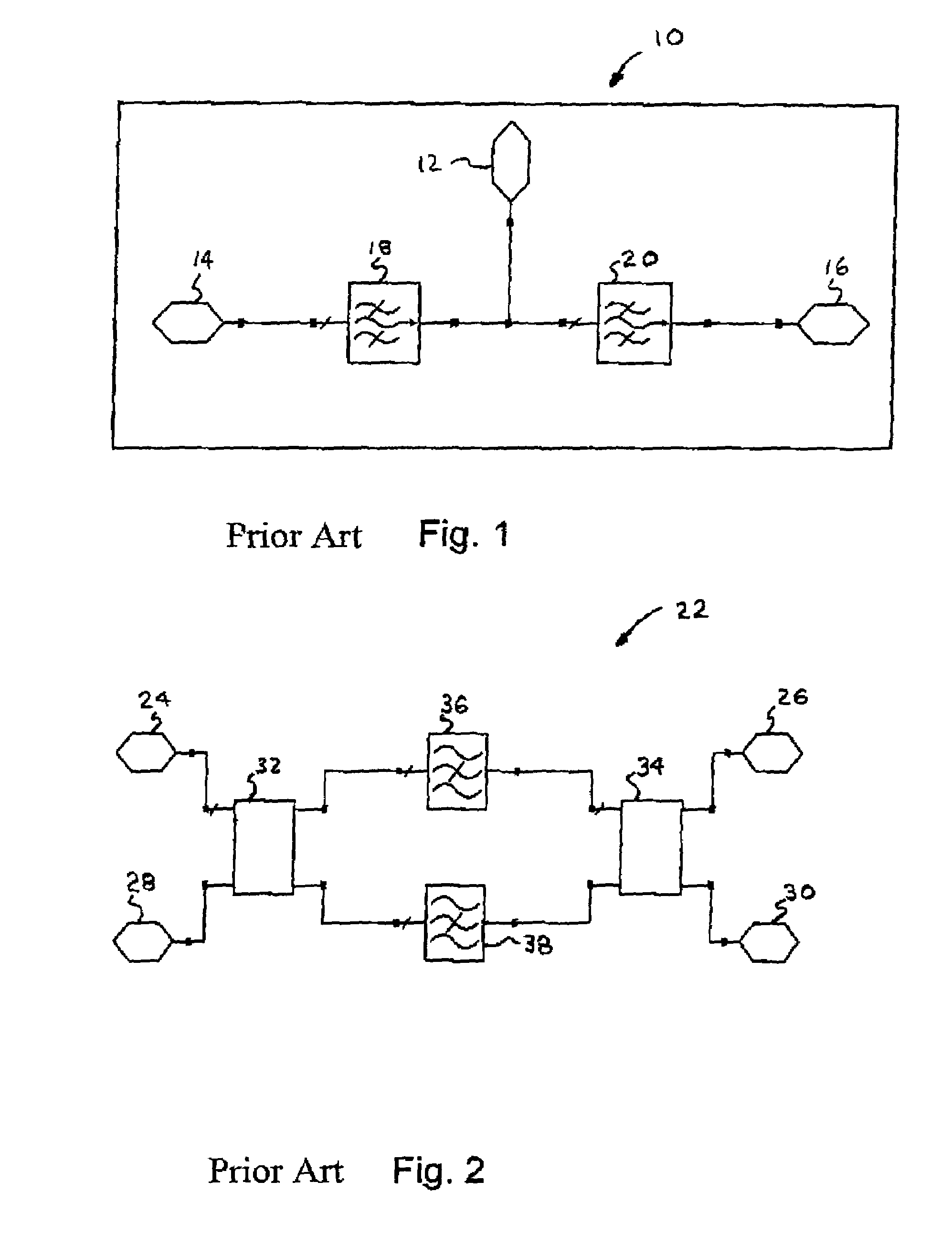
[0028]Today's standard duplexer 10 is shown in FIG. 1. It is a passive RF component with three ports: a transmitter port 14, a receiver port 16 and the antenna port 12. Two band-pass filters 18 and 20 are necessary in order to isolate the transmitter port 14 and the receiver port 16. In theory, no power coming from the transmitter 14 port must pass through to the receive port 16. The frequency of the transmitter is offset from that of the receiver

[0029]Another type of duplexer 20 is shown in FIG. 2. Duplexer 22 uses two hybrids 32 and 34 and two band-stop filters 36 and 38 in a chamber filled with liquid nitrogen at a temperature of 80 degrees Kelvin thus offering a low insertion loss by superconductivity. Duplexer 22 also includes a transmitter port 24, a receiver port 26, an antenna port 30, and a match load port 28. The two band-stop filters 36 and 38 are adjusted to reject the receiver frequencies. By using a substrate of LAO (LaAlO3), this duplexer gives an insertion loss of le...


PUM


Abstract

A duplexer for a communication device having a transmission unit, a reception unit and a shared antenna is disclosed. The duplexer comprises a first signal path between the transmission unit and the reception unit, the first signal path comprises a filter unit filtering the reception signal, the filtering unit provides a filtered signal to the reception unit. The duplexer further comprises a second signal path between the transmission unit and the reception unit. The second signal path comprises a cancellation unit which receives a sample of the transmission signal and produces a compensation signal. The injection of the compensation signal to the first signal path reduces the leakage signal, thereby producing a substantially leakage-free reception signal.

Description

FIELD OF THE INVENTION[0001]This invention relates to components for telecommunications devices. More particularly, the invention relates to duplexers between transmitters, receivers and antennas.BACKGROUND OF THE INVENTION[0002]The duplexer as it is known today gained significance around 1988. Before then, it was used for radars in the 50s, 60s and 70s. Some even contained gases. Today, the majority of the duplexers use dielectric materials having a quality factor, which results in a low insertion loss. They also use ceramic materials with a high permittivity in order to miniaturize the passive circuits.[0003]Over the years, the duplexer has evolved as follows:[0004]1953—Use of duplexers with cavities and in the configuration shown in FIG. 1. The cavities were in fact band-pass filters, which could be adjusted mechanically.[0005]1956—The duplexers were made from two hybrids and two tubes. The two tubes are filled with gas and play the role of a switch. These duplexers could not sen...

Claims


Application Information

Patent Timeline
12 Feb 2008
Publication
US7330500B2
IPC
H04B1/38; H04B1/48; H04B1/52; H04L5/14
CPC
H04B1/525
Inventors
KOUKI, AMMAR B.