
Buffer memory management method and system

a buffer memory and memory management technology, applied in the field of buffer memory management, can solve the problems of affecting the quality of communication and voice transmission experienced by end users, and not being able to perform processing necessary, and achieve the effect of maximizing the utilization of buffer memory hardware resources

Inactive Publication Date: 2008-02-12
FUJITSU LTD
View PDF13 Cites 39 Cited by
  • Summary
  • Abstract
  • Description
  • Claims
  • Application Information

AI Technical Summary

Benefits of technology

[0022]Hence an object of this invention is to provide a packet buffer management method and system which, compared with conventional packet buffer management methods, enable maximum utilization of buffer memory hardware resources, and are optimal for the preset number of physical ports used and number of CoS areas.
[0023]A further object of this invention is to enable excellent processing performance of various packet operations through comparatively simple hardware.

Problems solved by technology

In recent years the amount of traffic of data such as voice and images, which emphasize realtime response, on IP (Internet Protocol) networks has been increasing; and packet states such as packet delays and losses in routers, switches and other devices performing packet exchange in networks have greatly impacted the quality of communication and voice transmission experienced by end users.
Further, in the conventional buffer management method the amount of movement of the management pointer-based on settings in the service class characteristic table 8 is fixed, so that it is not possible to perform processing necessary for substitution of the order of transfer of packets in the packet output control portion 11, for intentional loss of arbitrary packets, or to otherwise simulate network operation.

Method used


Image

  • Buffer memory management method and system
  • Buffer memory management method and system
  • Buffer memory management method and system

Examples


Embodiment Construction

[0052]Below, aspects of the invention are explained.

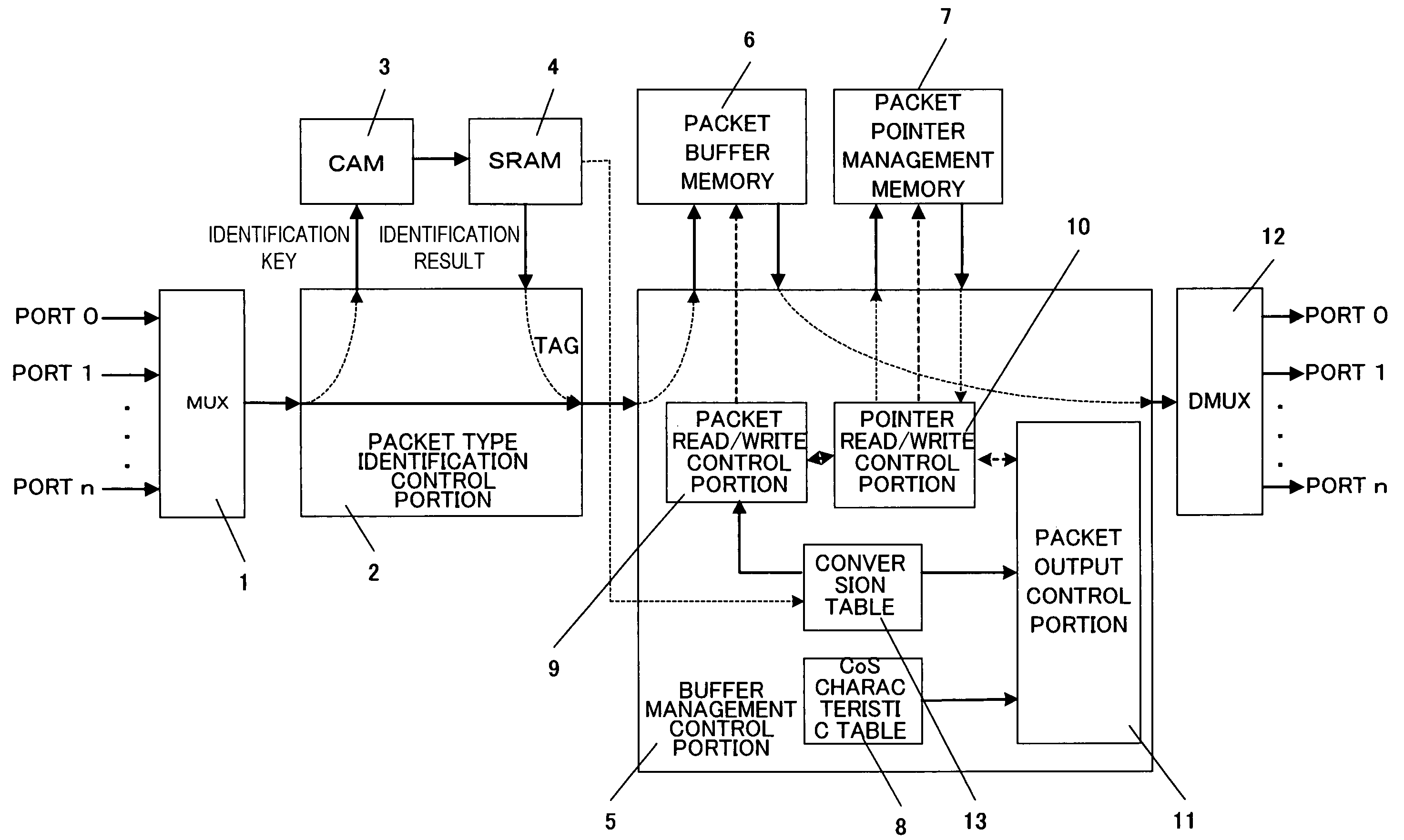
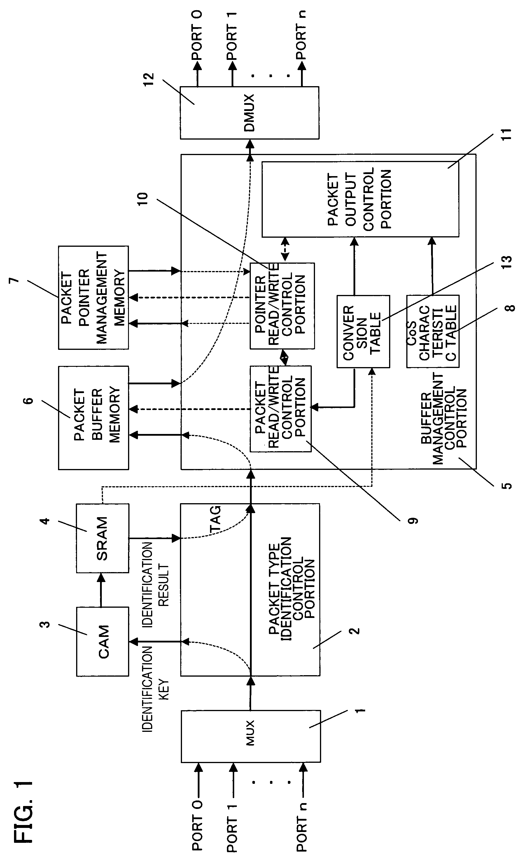
[0053]FIG. 1 is a block diagram of an aspect of a simulation device to simulate network quality, to which a buffer management method of the present invention is applied. In comparison with the conventional configuration shown in FIG. 17, the simulation device of the present invention has the feature of including a conversion table 13.

[0054]In the following explanations, it is assumed that there are 0th through nth network physical ports, 0 through N IP addresses for CoS identification, and 0 through M types of CoS characteristics.

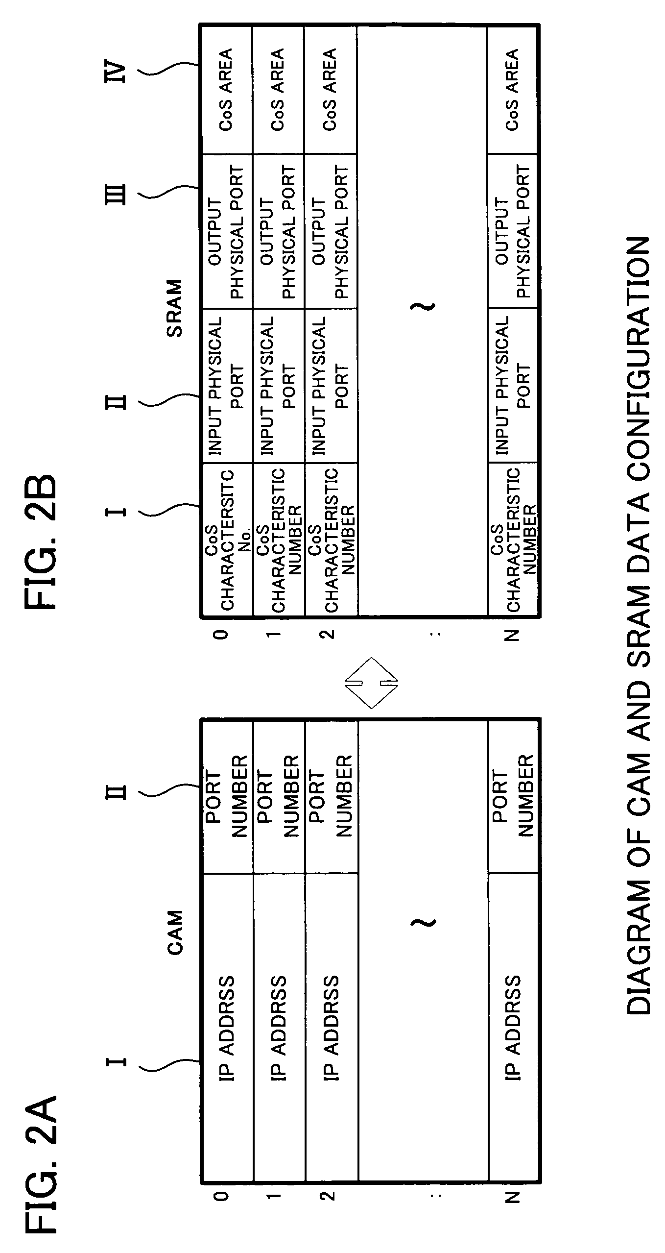
[0055]In FIG. 1, the multiplexing portion 1 multiplexes the Ethernet signals of a plurality n of ports. The packet type identification control portion 2 has CAM 3 and SRAM 4, and compares the IP address or other identification information in the header portion of a packet multiplexed by the multiplexing portion 1 with registered information, referring to the associative memory (CAM: Content Addressable Mem...


PUM


Abstract

A packet buffer management method and system are provided which enable maximum utilization of the hardware resources of the buffer memory, and which are optimum for the number of preset physical ports in use or for the number of service class (CoS) areas. In the buffer memory management method in a packet transmission / reception device, for storing a received packet in the buffer memory and controlling writing and reading of packets to and from the above buffer memory, the control methods are set in units of the service class contained in the header portion of received packets, and areas allocated to each service class in the buffer memory storing received packets are modified according to the set number of the above service classes.

Description

BACKGROUND OF THE INVENTION[0001]1. Field of the Invention[0002]This invention relates to a method of management of buffer memory which stores packets in a network simulation device which simulates a device for performing packet exchange such as a router, and a buffer memory management system in a network simulation device using this method.[0003]2. Description of the Related Art[0004]In recent years the amount of traffic of data such as voice and images, which emphasize realtime response, on IP (Internet Protocol) networks has been increasing; and packet states such as packet delays and losses in routers, switches and other devices performing packet exchange in networks have greatly impacted the quality of communication and voice transmission experienced by end users.[0005]Hence there has been a need to perform simulations of network quality, using settings to simulate the creation of various packet states in networks.[0006]Buffer memory (hereafter called “packet buffers” for conve...

Claims


Application Information

Patent Timeline
IPC IPC(8): G06F5/00H04L12/70H04L12/801H04L12/861H04L12/911H04L13/08
CPCH04L47/24H04L47/2441H04L47/6215H04L49/90
Inventor YAMAMOTO, HIROAKIMIYAHARA, SEIJI
Owner FUJITSU LTD
Learn More