Electric cutting device

a cutting device and electric technology, applied in the field of electric cutting devices, can solve the problems of inflicting bodily injury to such people, many bodily injuries, etc., and achieve the effect of easily cutting up metal wires

Active Publication Date: 2008-02-19
WU HUNG YANG +1
View PDF13 Cites 20 Cited by
  • Summary
  • Abstract
  • Description
  • Claims
  • Application Information

AI Technical Summary

Benefits of technology

[0007]The present invention is to provide an electric cutting device that is used to cut up metal wires easily.
[0008]Another, the present invention is to provide an electric cutting device that is structurally simple, easy to manufacture and easy to use.

Problems solved by technology

In addition, the cutting of such thick metal wire may inflict a bodily injury to such person.
For example, during the assembly of a bouquet of artificial flowers (with the stems made of wires), many bodily injuries have been caused due to the use of such manually operated cutter.

Method used


Image

  • Electric cutting device
  • Electric cutting device
  • Electric cutting device

Examples


Embodiment Construction

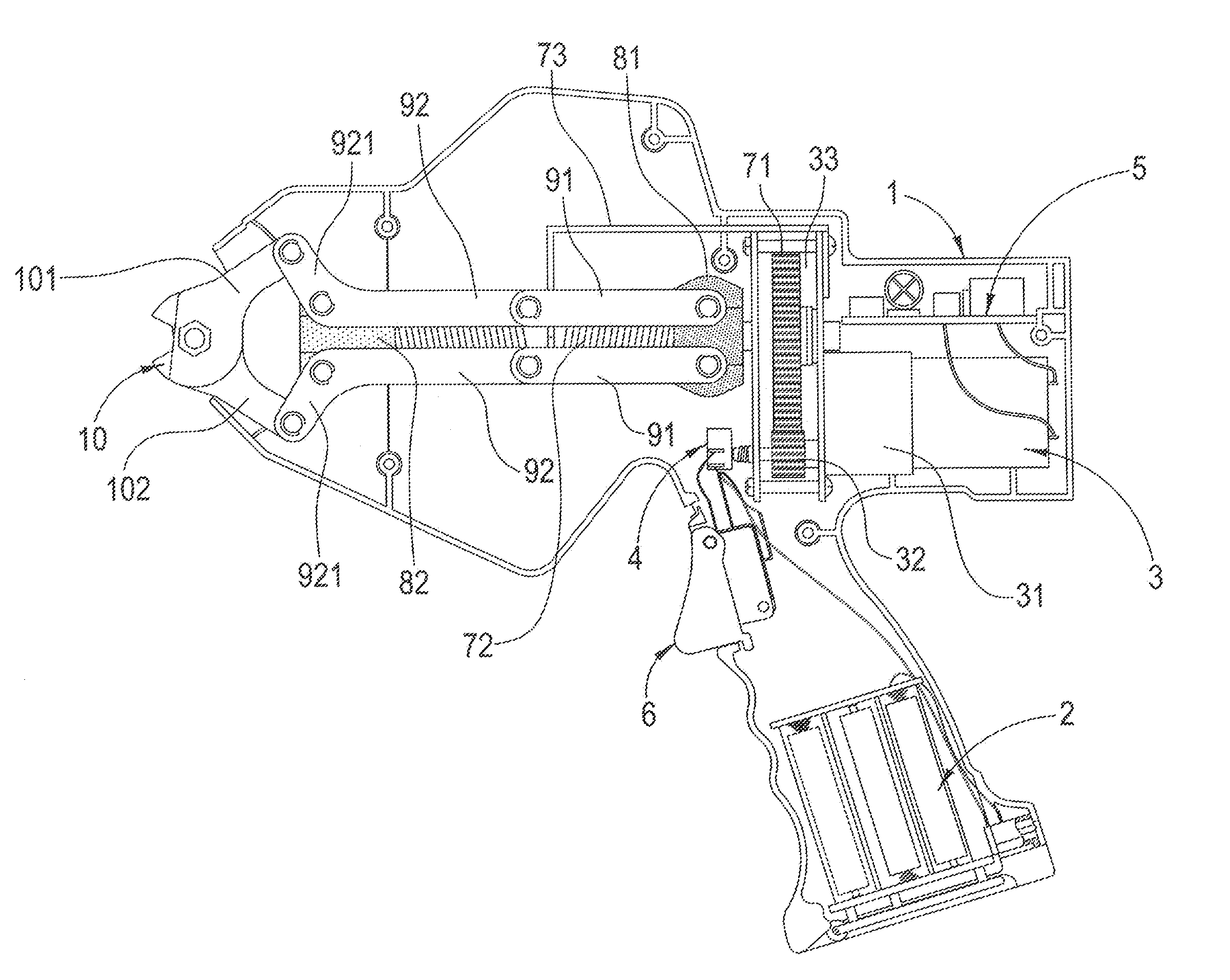
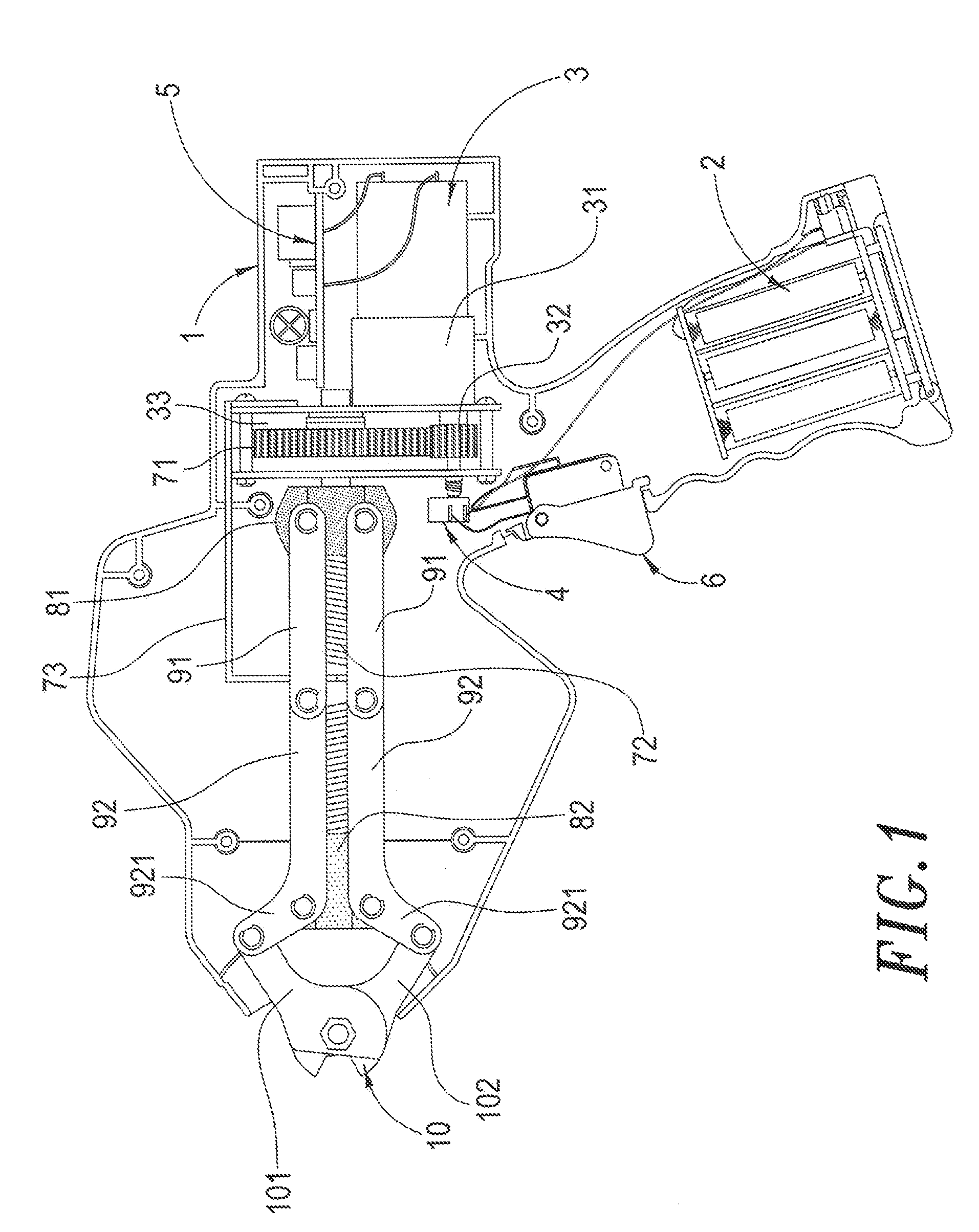
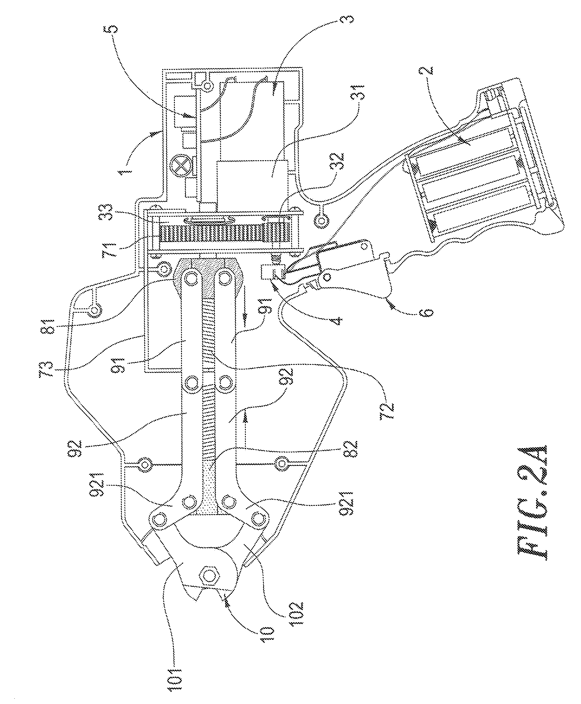
[0013]As illustrated in FIG. 1, the electric cutting device of the present invention comprises a housing 1, a motor 3, a power switch 4, an activation button 6, a control circuit 5, a driving gear 71, a threaded rod 72, a separation plate 73, a first assembly 81, a second assembly 82, two supporting rods 91, two connecting rods 92 and a cutting assembly 10.

[0014]A power supply unit 2 is disposed in the lower portion of the housing 1. The power supply unit 2 may be a regular battery, a lithium battery or a power source outside of the electric cutting device.

[0015]The motor 3 is disposed in the housing 1. The output shaft of the motor 3 is connected with a speed reduction gear set 31 so as to increase the torque output from the motor 3. Also, a transmission gear 32 is connected with the output shaft of the speed reduction gear set 31 and is disposed in a space 33 provided in front of the speed reduction gear set 31.

[0016]The power switch 4 extends out of the housing 1. The power switc...


PUM

PropertyMeasurementUnit
poweraaaaaaaaaa
hardaaaaaaaaaa
thickaaaaaaaaaa

Abstract

An electric cutting device includes a housing, a motor, an activation button, a first assembly, a second assembly, two connecting rods, two connecting rods and a cutting assembly. The activation button may be used to activate the motor. The motor is connected with a speed reduction gear set, and a transmission gear is connected with the output shaft of the speed reduction gear set. The transmission gear is engaged with a driving gear. A threaded rod is fixedly connected with the driving gear. The two supporting rods are pivotally connected with the first assembly. The rear end of either connecting rod is connected with the front end of the corresponding supporting rod. In use, the motor may cause the threaded rod to rotate and then activate the cutting operation of the cutting assembly.

Description

BACKGROUND OF THE INVENTION[0001]1. Field of the Invention[0002]The invention generally relates to an electric cutting device. More particularly, the invention relates to an electric cutting device that is electrically operated and can be used to cut up metal wires and other objects easily.[0003]2. Description of the Prior Art[0004]As of now, people use various types of tools to assemble household products and furniture by themselves. Some of the tools (such as power drill) have been developed into an electric tool; however, some of them (such as cutter) still remain a manually operated tool. During assembly, a person may use a cutter to cut up metal wires and other hard objects. If a thick metal wire is to be cut by such cutter, the person needs to use more force and more time to cut it up. In addition, the cutting of such thick metal wire may inflict a bodily injury to such person. For example, during the assembly of a bouquet of artificial flowers (with the stems made of wires), ...

Claims


Application Information

Patent Timeline
Patent Type & Authority Patents(United States)
IPC IPC(8): B26B17/00B26B15/00B26B13/00
CPCB23D29/002B26B15/00
Inventor TU, SHU-WOAN
Owner WU HUNG YANG
Why Eureka
Try Eureka