Brake booster with deformationally sealed passage and method of manufacture

a technology of deformation sealing and brake booster, which is applied in the direction of reciprocating piston engines, positive displacement engines, cylinders, etc., can solve the problems of requiring a relatively complex, and thus costly, manufacturing process, and ensuring the vacuum seal of the housing when installing the tube, so as to simplify the manufacture of the brake booster and minimize the possibility of incorrect installation. , the effect of simplifying the assembly of the brake booster

Inactive Publication Date: 2008-02-19
DELPHI TECH INC +1
View PDF12 Cites 13 Cited by
  • Summary
  • Abstract
  • Description
  • Claims
  • Application Information

AI Technical Summary

Benefits of technology

[0013]An advantage of the present invention is that it provides a brake booster apparatus and a method of manufacturing a brake booster having an elongate hollow member that does not require a separate O-ring or other sealing member to seal the interface between hollow member and connectors located on opposite walls of the housing thereby simplifying the manufacture of the brake booster.
[0014]Another advantage, for some of the embodiments of the invention, is that the hollow member may have similarly configured opposite ends so that the hollow member can be installed without regard to the orientation of the its ends thereby simplifying the assembly of the brake booster and minimizing the possibility of incorrect installations of the hollow member.

Problems solved by technology

One of the disadvantages associated with this method of installing a brake booster is that it requires a relatively complex, and thus costly, manufacturing process to provide the passages that extend through the brake booster housing.
More specifically, ensuring the vacuum seal of the housing when installing the tube is often relatively complex.

Method used


Image

  • Brake booster with deformationally sealed passage and method of manufacture
  • Brake booster with deformationally sealed passage and method of manufacture
  • Brake booster with deformationally sealed passage and method of manufacture

Examples


third embodiment

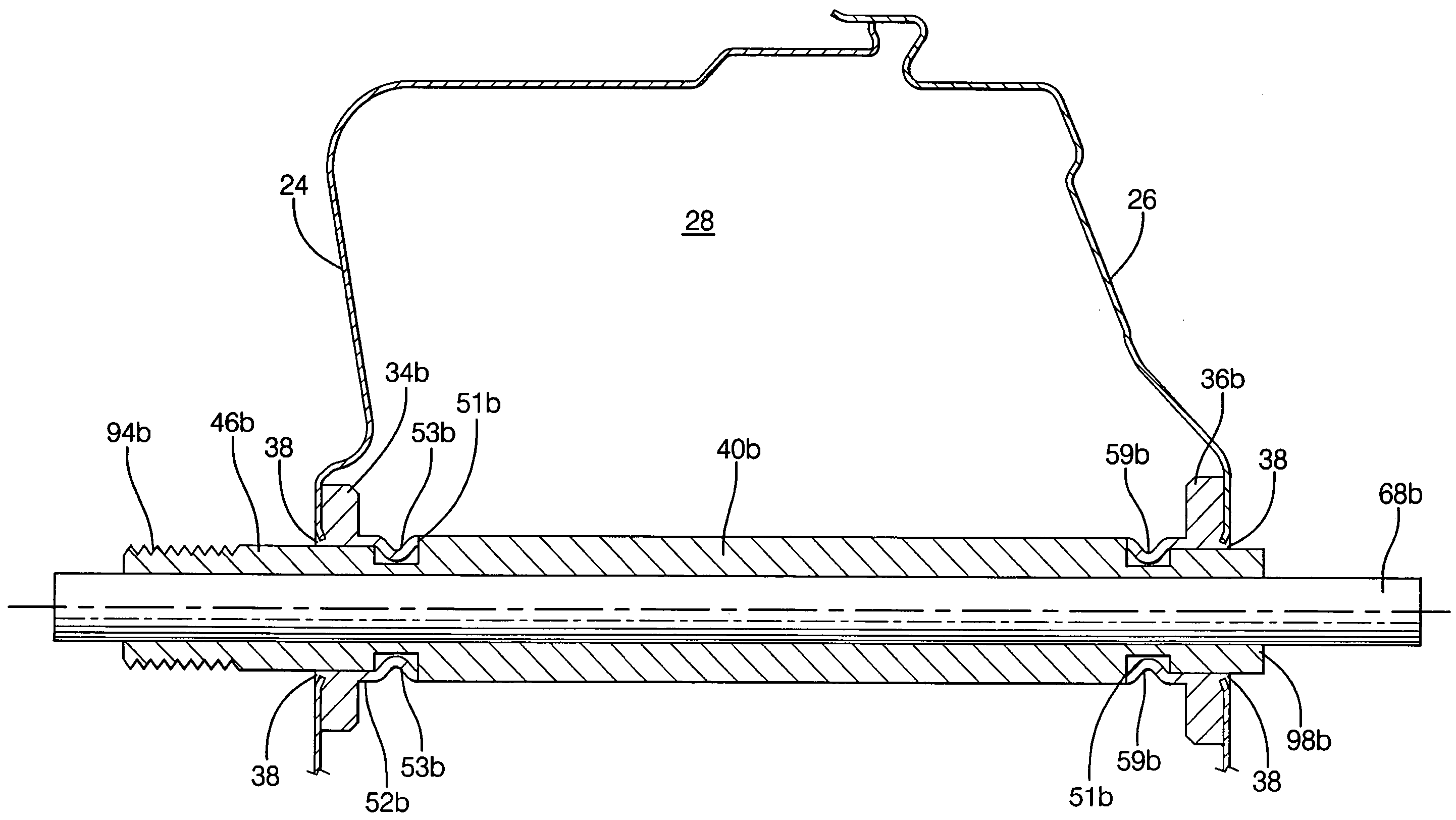
[0047]the invention is illustrated in FIGS. 9-11 and employs hollow member 40b and connectors 34b, 36b. In this embodiment, a portion of connectors 34b, 36b is deformed when securing hollow member 40b to the connectors 34b, 36b. As seen in FIG. 9, hollow member 40b has a passage 42b extending therethrough and defines a longitudinal axis 44b. The opposing end portions 46b, 48b of hollow member 40b respectively terminate at axial end surfaces 50b, 56b. Hollow member 40b also includes first and second radially outwardly opening annular recesses 104, 108 that are respectively disposed proximate axial end surfaces 50b, 56b. That portion of hollow member 40b located between annular recesses 104, 108 has a relatively large outer diameter that is greater than the outer diameter of end portions 46b, 48b located longitudinally outwardly of recesses 104, 108. This allows the distal portion of end portions 46b, 48b to be inserted through connectors 34b, 36b and also allows the inner sidewalls o...

first embodiment

[0049]Projecting portions 52b, 58b are deformed radially inwardly by the forcible engagement of axial end surfaces 51b, 57b with abutment surfaces 106, 110 respectively. Tooling 66b is used to forcibly press the connectors into engagement with hollow member 40b as schematically represented by arrows 70b in FIG. 10. Tooling rod 68b is used to ensure that hollow member 40b is not bent out of alignment during the engagement of hollow member 40b with connectors 34b, 36b. The resulting deformed portions 53b, 59b project into annular recesses 104, 108 where they engage hollow member 40b and thereby mechanically attach and form a seal between hollow member 40a and connectors 34b, 36b. After hollow member 40b and connector 36b are joined together, connector 34b is joined to the opposite end of hollow member 40b as best understood with reference to FIG. 11. Connector 34b is joined to housing section 24 before being joined to hollow member 40b and, thus, housing sections 24 and 26 are sealing...


PUM


Abstract

A brake booster apparatus having a housing with oppositely disposed first and second walls. A first connector is disposed in the first wall and a second connector is disposed in the second wall. An elongate hollow member is deformationally engaged to each of the first and second connectors. The various embodiments of the invention include embodiments wherein the hollow member is deformed to engage the hollow member and connectors and embodiments wherein the first and second connectors are deformed to engage the hollow member and connectors. The deformational engagement mechanically attaches and sealingly engages the hollow member with each of the first and second connectors. The hollow member defines a passage through the apparatus from the first wall to the second wall of the housing. A method of manufacturing a brake booster is also disclosed.

Description

BACKGROUND OF THE INVENTION[0001]1. Field of the Invention[0002]The present invention relates to brake boosters and, more particularly, to a brake booster having a passage extending through the brake booster and methods of manufacturing such brake boosters.[0003]2. Description of the Related Art[0004]Many automobiles and light trucks employ a vacuum brake booster that increases the thrust force applied to the brake pedal by the operator of the vehicle. This increased force is imparted to the master cylinder to thereby provide a power-assisted braking system. Typically, the brake booster is attached to the firewall separating the engine compartment from the passenger compartment. The master cylinder is generally mounted on the brake booster opposite the firewall.[0005]Different methods have been employed when mounting the brake booster to the firewall. One of the commonly employed methods involves providing one or more tubular passages that extend through the brake booster between th...

Claims


Application Information

Patent Timeline
Patent Type & Authority Patents(United States)
IPC IPC(8): F16J10/02
CPCB60T13/5675
Inventor SEXTON, ROGER S.CASTEL, PHILIPPE G.
Owner DELPHI TECH INC
Why Eureka
Try Eureka