Dispense pump with heated pump housing and heated material reservoir

a technology of heated pump and reservoir, which is applied in the direction of liquid handling, movable measuring chambers, instruments, etc., can solve the problems of mechanical complexity, affecting the reliability of dispensing operation, and complicated configuration, and achieve reliable and efficient heating of materials.

Active Publication Date: 2008-02-19
DL TECH
View PDF129 Cites 49 Cited by
  • Summary
  • Abstract
  • Description
  • Claims
  • Application Information

AI Technical Summary

Benefits of technology

[0011]The present invention is directed to a heated dispense pump that overcomes the limitations of the conventional systems set forth above. In particular, the present invention provides for a reliable and efficient heating of the material in a system that is compact, lightweight, and accurate.
[0012]The present invention includes a pump housing and cartridge body that are formed of a thermally conductive material such as copper, aluminum, or an alloy combination thereof. A heater element is applied directly to the body of the pump housing, and a thermocouple is included to provide for closed-loop controllability. The material flows though the cartridge body and is heated prior to release at the dispense tip. The heated elements, including the pump housing and cartridge body, are thermally insulated from the pump motor and pump gantry to prevent the escape of heat from the system and to protect those components from heat damage.

Problems solved by technology

However, this approach leads to a more complicated configuration that is difficult to clean.
However, this approach is mechanically complex, and involves the movement of air above components, which can affect the reliability of the dispensing operation.
In addition, due to the tolerances of the cylinder, air gaps can form between the inner circumference of the cylinder and the body of the pump, leading to inaccurate and inefficient heating.

Method used


Image

  • Dispense pump with heated pump housing and heated material reservoir
  • Dispense pump with heated pump housing and heated material reservoir
  • Dispense pump with heated pump housing and heated material reservoir

Examples


Embodiment Construction

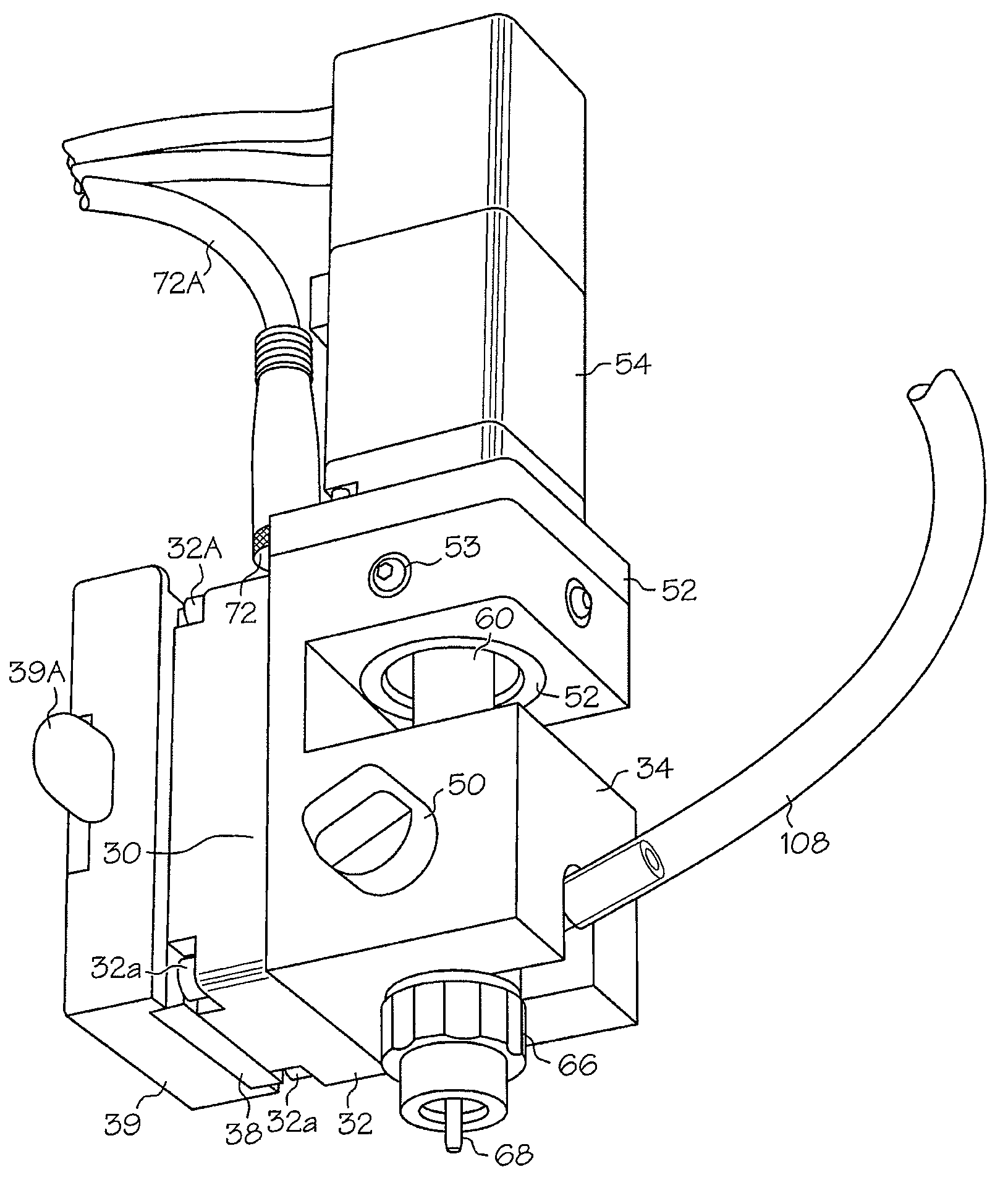
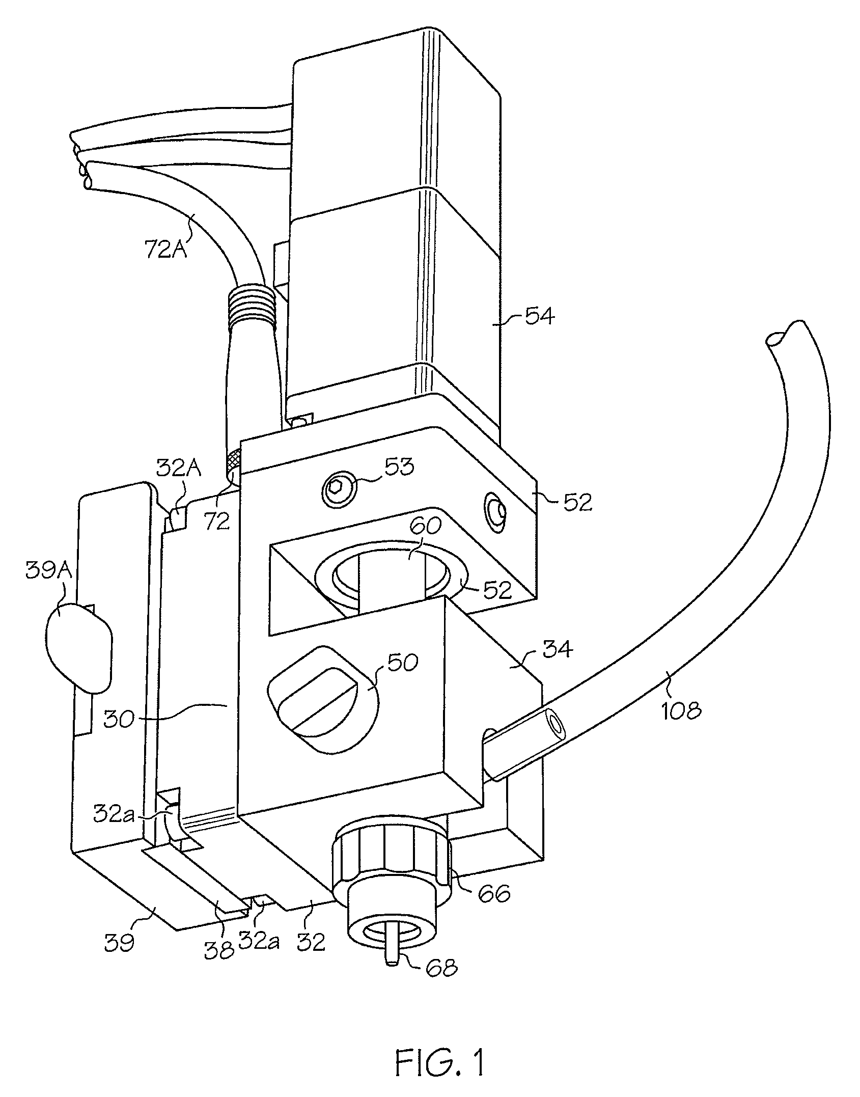
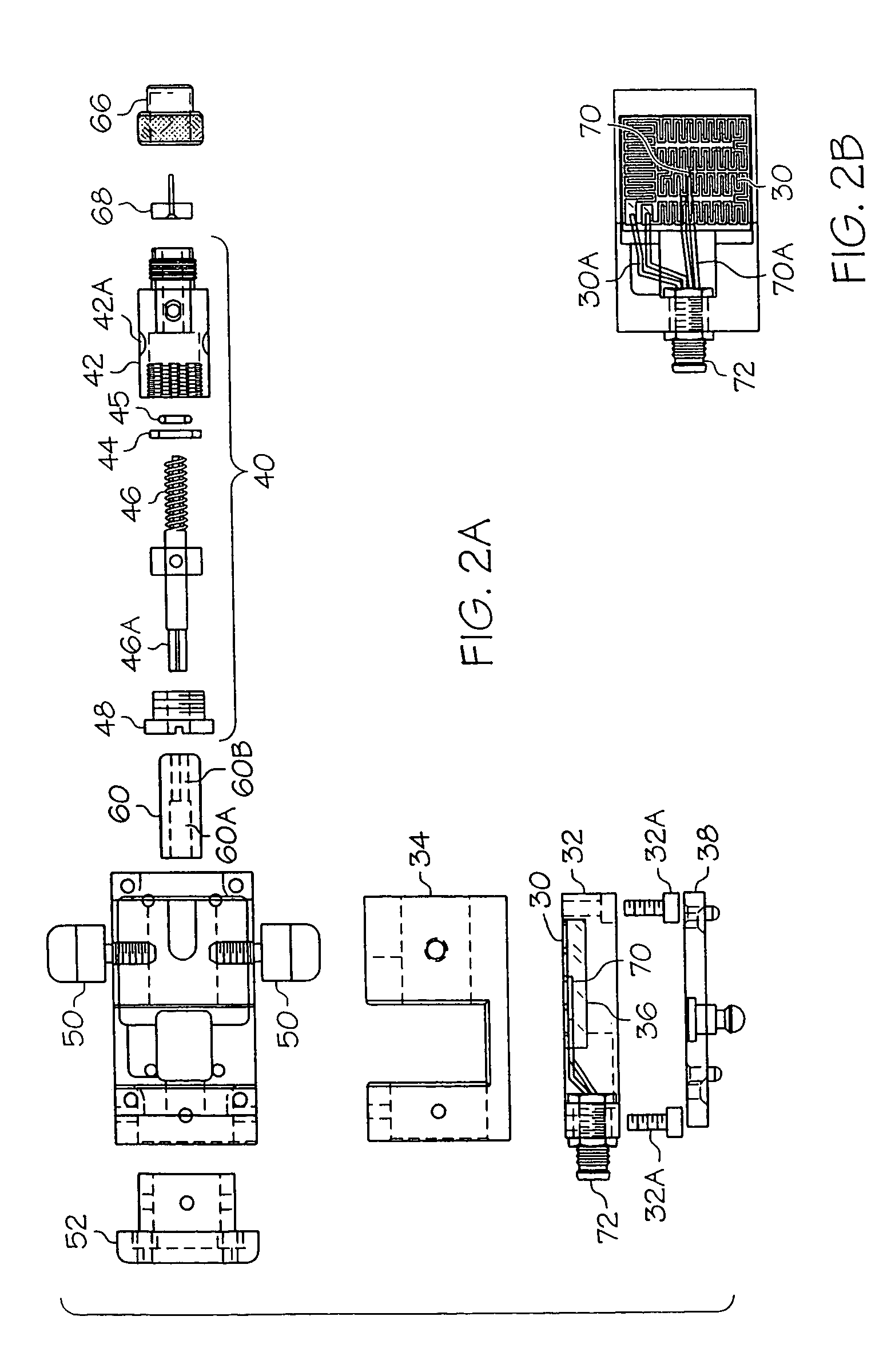
[0034]FIG. 1 is a perspective view of a heated fluid dispense pump assembly configured in accordance with the present invention. FIG. 2A is an exploded top side view of the heated fluid dispense pump assembly of FIG. 1 in accordance with the present invention. FIG. 2B is a side view of the pump body heater of FIG. 2A, in accordance with the present invention.

[0035]The components and operation of the dispense pump depicted in FIGS. 1 and 2 are similar in form and purpose to those disclosed in the embodiments of the patent applications referenced above, and incorporated herein by reference. The dispense pump includes a pump housing or body 34, a motor 54, and a cartridge assembly 40. A coupling 60 includes a first opening 60A that interfaces with an axle of the motor 54 and includes a second opening 60B that interfaces with a top portion 46A of the auger screw 46. The motor 54 and cartridge assembly 40 are mounted to the pump housing 34 and communicate via the coupling 60 such that ro...


PUM


Abstract

A heated dispense pump overcomes the limitations of conventional systems providing for reliable and efficient heating of the dispensed material in a system that is compact, lightweight, and accurate. A pump housing and cartridge body are formed of a thermally conductive material such as copper, aluminum, or an alloy combination thereof. A heater element is applied directly to the body of the pump housing, and a thermocouple is included to provide for closed-loop controllability. The material flows though the cartridge body and is heated prior to release at the dispense tip. The heated elements, including the pump housing and cartridge body, are thermally insulated from the pump motor and pump gantry to prevent the escape of heat from the system and to protect those adjacent components from heat damage. An optional syringe heater is provided for heating the material in the syringe, and for controlling the temperature of the material, in closed-loop fashion. In this manner, the temperature of the material in the syringe and the temperature of the material in the pump can be controlled independently of each other.

Description

RELATED APPLICATIONS[0001]This application claims the benefit of U.S. Provisional Patent Application Ser. No. 60 / 546,886, filed Feb. 23, 2004 and U.S. Provisional Patent Application Ser. No. 60 / 458,528, filed Mar. 28, 2003, the contents of which are incorporated herein by reference, in their entirety.[0002]This application is related to U.S. patent application Ser. No. 10 / 424,273, filed Apr. 28, 2003, now U.S. Pat. No. 6,983,867; U.S. patent application Ser. No. 10 / 295,730, filed Nov. 15, 2002, now U.S. Pat. No. 6,851,923; U.S. patent application Ser. No. 10 / 054,084, filed Jan. 22, 2002, now U.S. Pat. No. 6,892,959; U.S. patent application Ser. No. 10 / 038,381, filed Jan. 4, 2002, now U.S. Pat. No. 6,957,783; and U.S. patent application Ser. No. 09 / 702,522, filed Oct. 31, 2000, now U.S. Pat. No. 6,511,301, the contents of each being incorporated herein by reference, in their entirety.BACKGROUND OF THE INVENTION[0003]Contemporary fluid dispense systems are well suited for dispensing p...

Claims


Application Information

Patent Timeline
Patent Type & Authority Patents(United States)
IPC IPC(8): B67D5/63G01F11/22B67D7/82
CPCB05C5/001B05C5/02
Inventor FUGERE, JEFFREY P.
Owner DL TECH
Why Eureka
Try Eureka