X-ray examination apparatus that is convertible among multiple examination configurations

a technology of x-ray examination apparatus and configuration, applied in the field of x-ray system, can solve the problems of insufficient utilization of under-table system, high cost of installation of several imaging devices,

Inactive Publication Date: 2008-02-19
SIEMENS HEALTHCARE GMBH
View PDF19 Cites 27 Cited by
  • Summary
  • Abstract
  • Description
  • Claims
  • Application Information

AI Technical Summary

Benefits of technology

[0010]Using this radiation protection device and the operation unit installed directly on the patient examination table, the operator is provided with a system control that is close to the patient, and also with protection from radiation analogous to that of an undertable system; i.e., the technician can operate the system exactly like an undertable system with the added advantage of the better image geometry of an overtable system.
[0011]The X-ray system preferably also has a remote control unit with which to operate the system components from an adjoining room. With this configuration, the system can be alternatively operated as a conventional undertable system or as an overtable system. Therefore, the installation of two independent X-ray systems in different rooms is no longer necessary. The system is better utilized and always provides an optimal image geometry.
[0013]The radiation protection device and the operation unit preferably are mounted on the patient examination table so that they can be shifted in the longitudinal direction of the patient examination table. With this adaptability, the operator can optimally set the position of the radiation protection device and his / her own position with respect to the region in the patient's body to be examined.
[0021]The X-ray radiator preferably hangs from a generator stand, which is designed in such a manner that the X-ray radiator is adjustable in at least three (orthogonal) spatial directions, and can be swiveled around its vertical and horizontal axes. The combination of any desired swiveling and adjustment possibilities of the image acquisition unit and the extensively variable positioning of the X-ray radiator make it possible to irradiate the patient from various directions, which is currently only possible when using a C-arm unit,
[0022]Furthermore, the stand preferably is designed so that the X-ray radiator also can be moved to a position outside the area above the patient examination table. If the X-ray generator can be moved beside the patient examination table, using a mobile detector or a conventional film cassette, X-ray images can be made even of a patient lying in a hospital bed without having to transfer the patient to an examination table. The stand preferably is designed so that the X-ray generator also can be positioned directly in the side of the patient examination table and swiveled around the horizontal axis a sufficient amount so that transverse images of a patient lying on the table can be obtained after, as already described, the image acquisition unit has been brought to a position to the side of and above the patient examination table.
[0027]Furthermore, the control device preferably is designed so that, during positioning of the examination table, the X-ray radiator is automatically moved in such a manner that—in relation to the table—the set-up position and the set-up radiation angle of the central X-ray beam remain constant. Thus, using this control device, the X-ray system can be used as a C-arm device and, therefore, can fully substitute for it. Since the coupling is done electronically and—unlike a C-arm device—no mechanical connection is required between the X-ray radiator located above the patient examination table and the image acquisition unit located underneath the patient examination table, complete access to the table from all sides is guaranteed.

Problems solved by technology

It is clear that an installation with several imaging devices—especially if these instruments are up-to-date, including expensive dynamic flat detectors—is very costly.
Although, generally the various devices can be used in parallel practice shows that, in a joint consulting room, for example, several physicians use the overtable system for their examinations, whereas the undertable system is not sufficiently utilized (or vice versa).
Thus, the result is that, at least temporarily, these instruments are not optimally used and, on the contrary, the staff and the patients face unnecessary waiting times.

Method used


Image

  • X-ray examination apparatus that is convertible among multiple examination configurations
  • X-ray examination apparatus that is convertible among multiple examination configurations
  • X-ray examination apparatus that is convertible among multiple examination configurations

Examples


Embodiment Construction

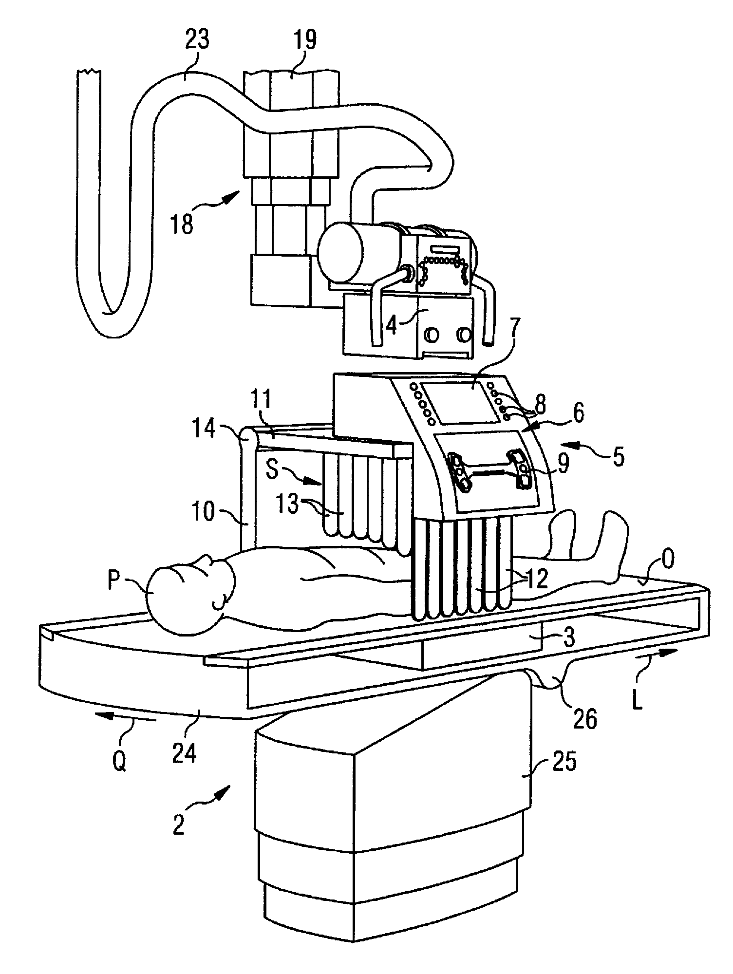
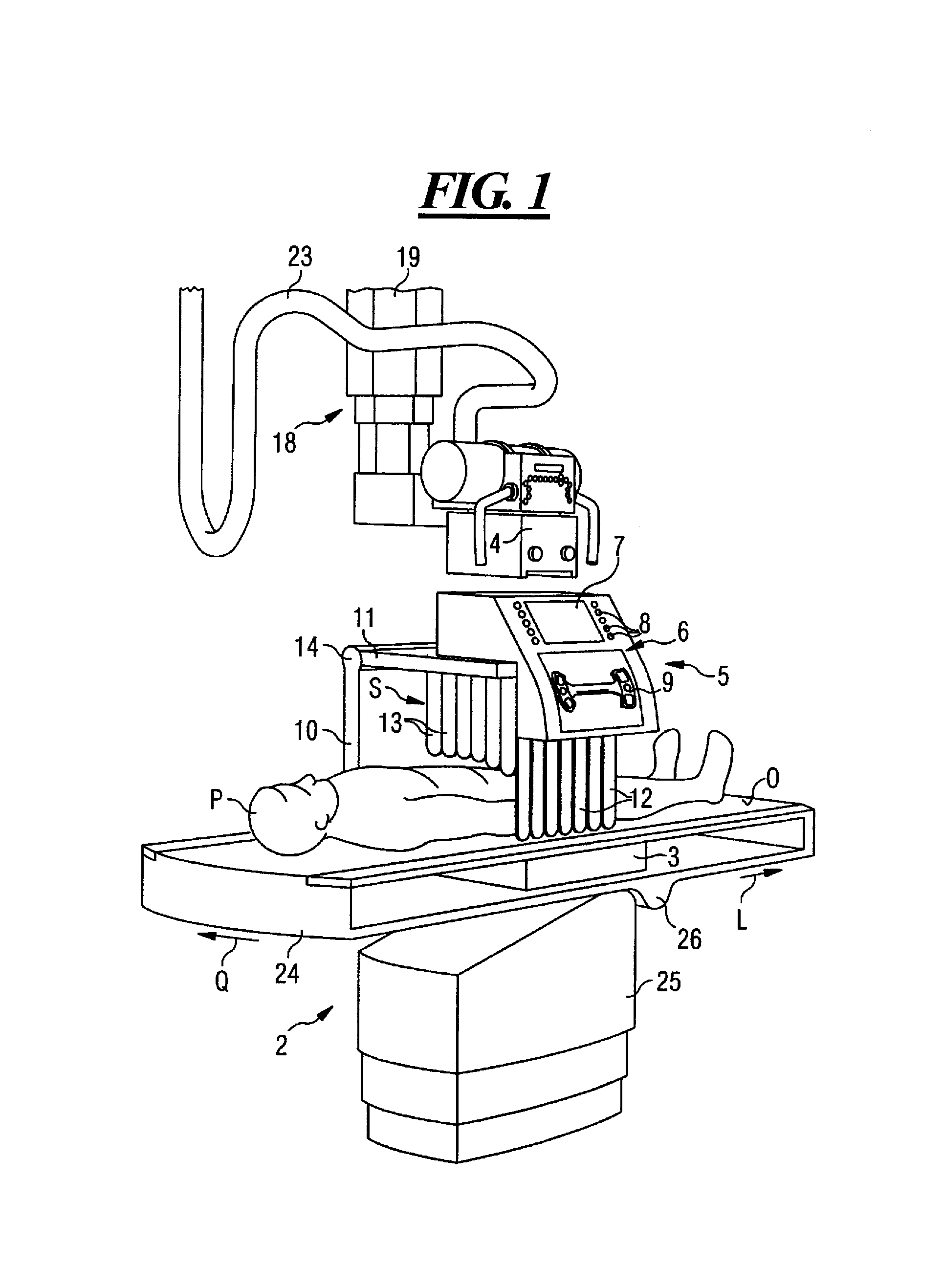
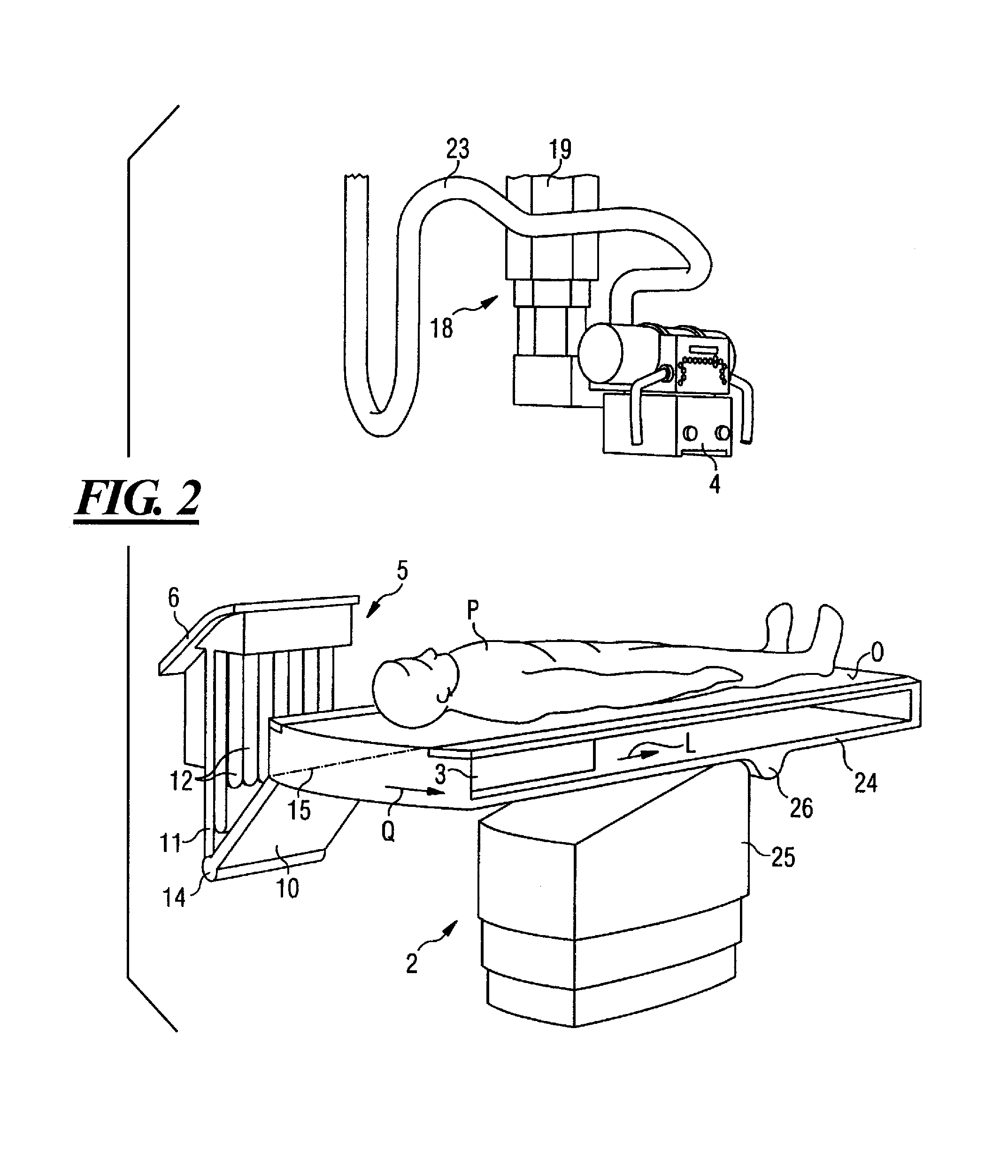
[0038]All the figures show the same universal X-ray system 1, which is can be substituted for a basic imaging device, an overtable device, an undertable device, and a C-arm device. For simplicity, not all the figures show all the components. So, for example, the power supply line 23, which leads from the top to the X-ray radiator 4, is shown only in FIGS. 1 and 2, and the control unit 27 for the positioning of individual components 2, 3, 4 is shown only in FIG. 7.

[0039]In addition to the illustrated components, the X-ray system 1 has one or more monitors on which the operator can view the image acquired by an image acquisition unit 3, here a flat detector 3. These monitors can be mounted, for example, on a second ceiling stand (not shown) beside the table 2. Also not shown are other components located outside the X-ray room, such as the main control console, additional monitors, etc., as well as other components required and usual for such a system, such as a voltage generator, imag...


PUM


Abstract

An X-ray system has a patient examination table, an image acquisition unit under the surface of the patient examination table, and an X-ray radiator that can be positioned above the patient examination table, On the patient examination table a radiation protection device is disposed, which—during the operation—shields at least one zone on one side of the patient examination table from the radiation area between the X-ray radiator and the image acquisition unit. In addition, on the patient examination table an X-ray system operation unit is disposed that is accessible from the shielded zone.

Description

BACKGROUND OF THE INVENTION[0001]1. Field of the Invention[0002]The invention relates to an X-ray system of the type having a patient examination table, an image acquisition unit underneath the surface of the patient examination table (such as a flat detector), and an X-ray generator mounted above the table.[0003]2. Description of the Prior Art[0004]An X-ray system of this described type is a typical so-called “overtable system”. Such an overtable system usually is controlled by means of a main control console located outside the X-ray examination room. The operator can watch the patient through a glass wall between the control room and the X-ray examination room, and interacts with the patient via a voice communication system. In addition to overtable systems, so-called “undertable systems” also are known, in which the X-ray generator is located underneath the table and the image acquisition unit, usually an image intensifier or a fluorescent screen, is mounted above the patient ex...

Claims


Application Information

Patent Timeline
Patent Type & Authority Patents(United States)
IPC IPC(8): H01J35/16A61B6/04A61B6/10
CPCA61B6/04A61B6/4464A61B6/548A61B6/107
Inventor FISCHER, KLAUSZERL, WOLFGANG
Owner SIEMENS HEALTHCARE GMBH
Why Eureka
Try Eureka