Method of stepless capacity control of a reciprocating piston compressor and piston compressor with such control

a reciprocating piston compressor and stepless technology, applied in the direction of pump control, positive displacement pump components, pump control, etc., can solve the problems of continuous irregular control, inability to have a substantial influence on the capacity control, etc., to achieve short switch-over time, minimal clearance volume, and simple and compact manner

Inactive Publication Date: 2008-02-19
HOERBIGER VENTILWERKE AKTIENGES
View PDF18 Cites 34 Cited by
  • Summary
  • Abstract
  • Description
  • Claims
  • Application Information

AI Technical Summary

Benefits of technology

[0020]Since sufficiently rapid-switching control valves can be realized only for small cross sections of the opening (f), an additional embodiment of the inventive compressor is advantageous according to which the clearance volume between control valve and unloading piston is maximal nearly equal or smaller than twice the stroke volume of the unloading cylinder.
[0021]In an additional preferred embodiment of the compressor according to the invention, the guide of the unloader and / or the control valve form one structural unit together with the unloading cylinder and / or the piston, which makes designs possible in a very simple and compact manner which are provided with a minimal clearance volume of the aforementioned type.
[0022]In an additional embodiment of the invention, the control valve is designed as a solenoid-actuated 3 / 2-port directional control valve and is preferably switched in such a manner that it acts upon the unloading cylinder with gas pressure while being without electric power. In case of failure of the control electronics for the valve, the compressor operates in this way with an open suction valve whereby through the decrease of gas pressure biasing the unloading cylinder, the unloader is pulled back and the compressor can be brought thereby to full power. Thus, emergency operation without continuous control is also possible.
[0023]The unloading cylinder can thereby be directly integrated or formed in one piece in combination of control valve and unloader. The control valve is positioned in direct proximity of the unloading cylinder within the suction valve or the unloader guide and forms a 3 / 2-port directional control valve. The valve switches over as desired the gas supply or the discharge (blowoff) line to the unloading cylinder. Because of the very short switch-over times and the high switching speeds, there occurs no considerable gas loss during the switch-over process (the embodiment corresponds thereby to a 3 / 3-port directional control valve whereby the center switching position is rapidly passed and cannot be directly triggered either.) A very rapid response and engagement of the unloader can be realized after each working cycle through the embodiment having a very small clearance volume due to short lengths of the line between the unloading cylinder and the control valve combined with the rapid-switching solenoid.

Problems solved by technology

On the other hand, the gas pressure biasing the unloading piston is no longer directly responsible for the closing crank angle—as long as this pressure lies only for all operational conditions or cited parameters above the gas pressure required to overcome the maximum possible reverse flow force—as a result, the fluctuation of the cited parameters cannot have a substantial influence on the capacity control.
An extension of the cited discharge time without a substantial negative influence on the possible range of control would make necessary a decrease of the gas pressure acting upon the unloading piston to a value just over the gas pressure required to overcome the maximal possible reverse flow force, which then causes again problems with outside parameters in influencing this gas pressure and it causes continuous irregularities in control.

Method used


Image

  • Method of stepless capacity control of a reciprocating piston compressor and piston compressor with such control
  • Method of stepless capacity control of a reciprocating piston compressor and piston compressor with such control
  • Method of stepless capacity control of a reciprocating piston compressor and piston compressor with such control

Examples


Embodiment Construction

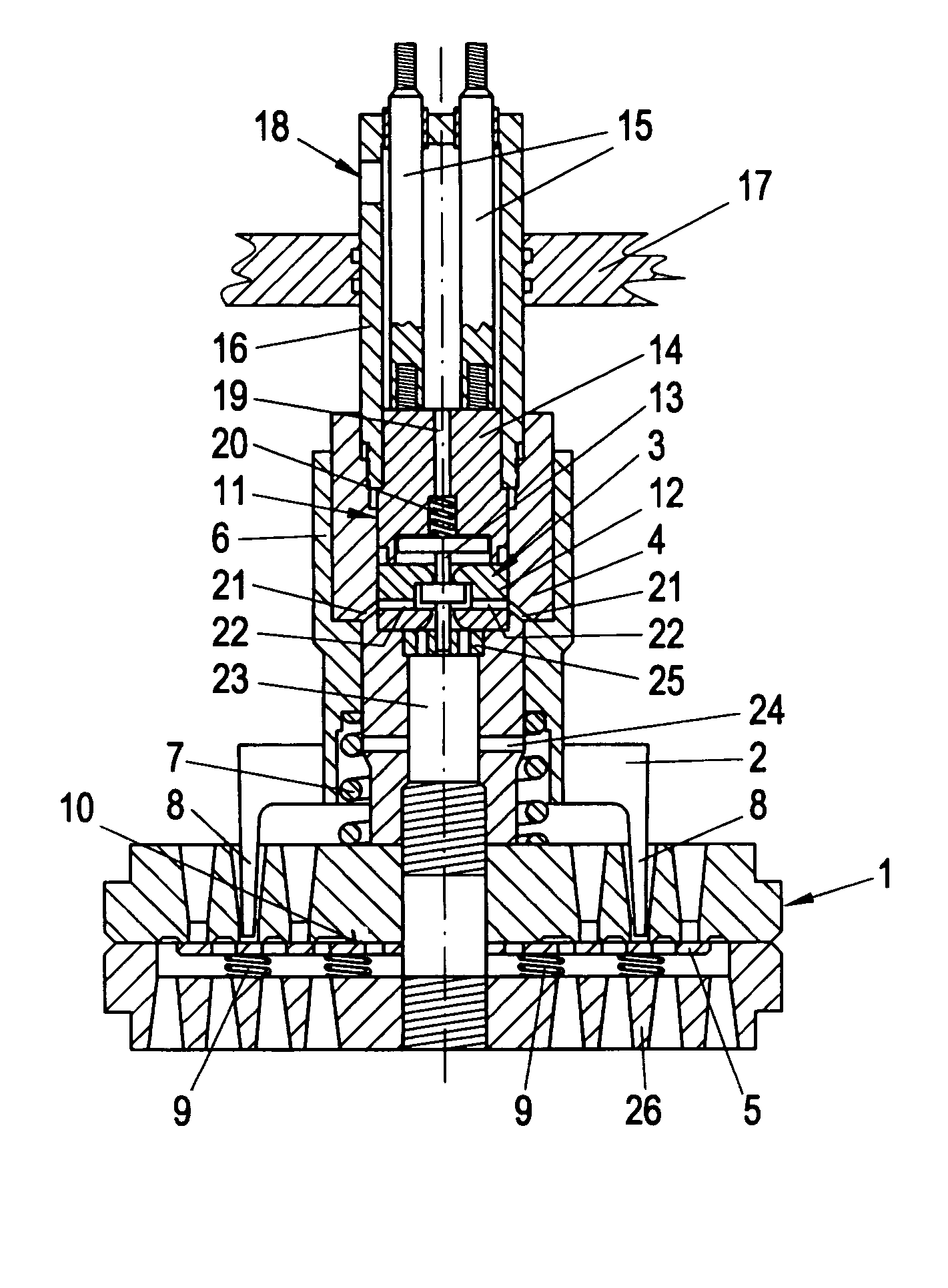
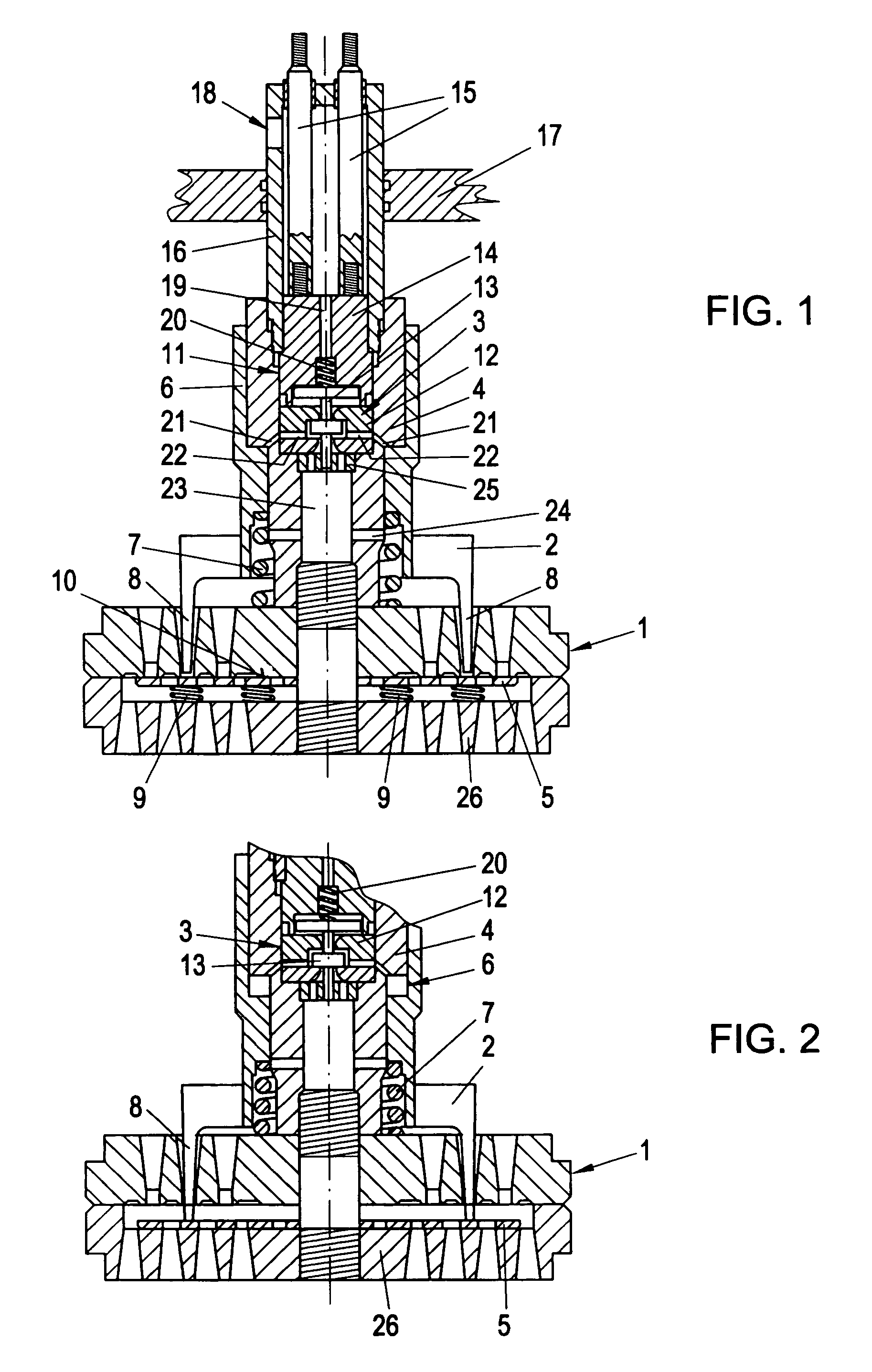
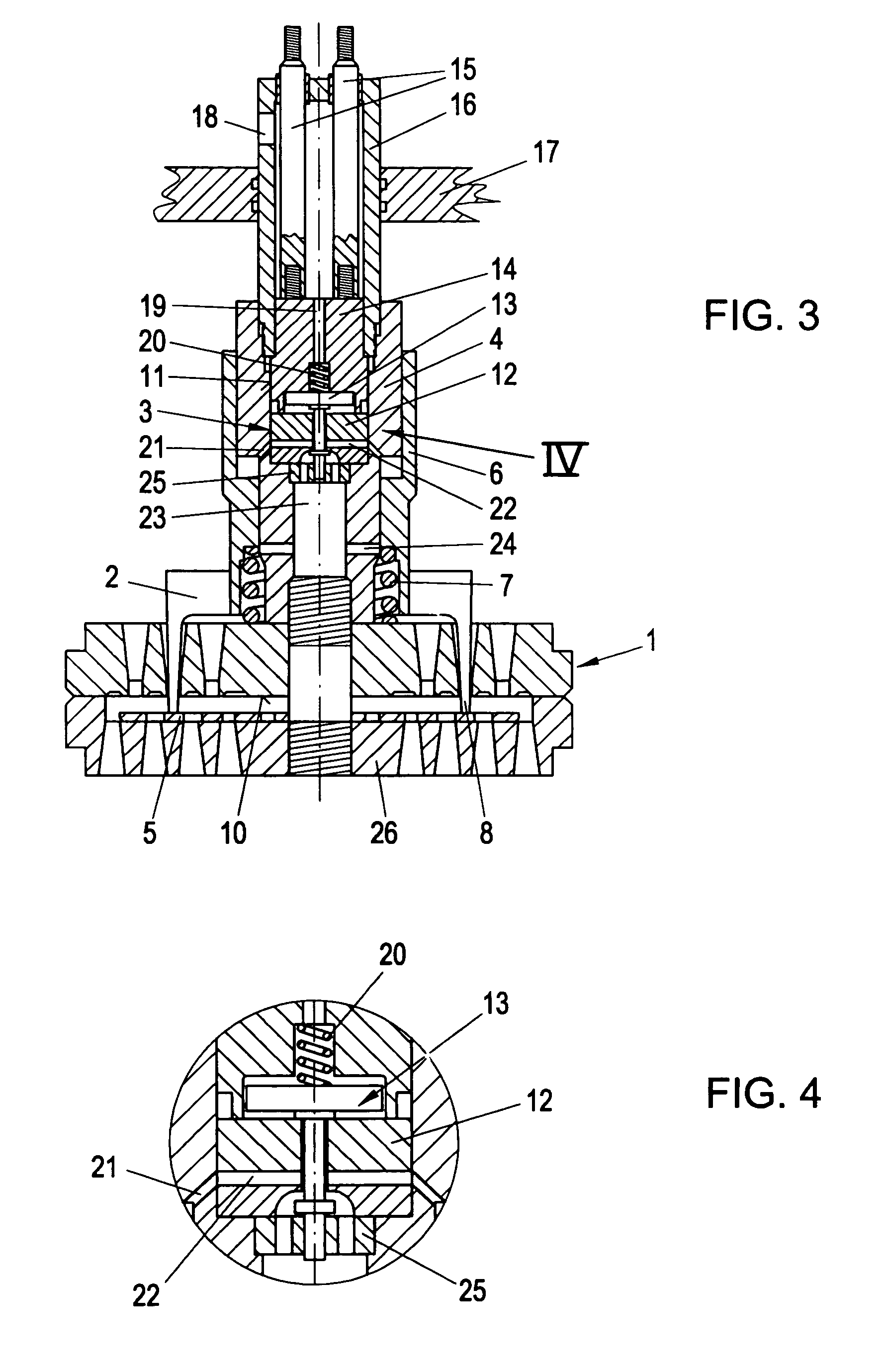
[0034]In all embodiments according to FIG. 1 through FIG. 6, an unloader 2 is arranged on the suction valve 1 of the compressor whereby the unloader 2 keeps at least one sealing element of the suction valve 1 over a thereby controllable portion of the working cycle of the compressor by means of an unloading piston 4 biased by gas pressure via a switchable control valve 3. The unloading piston 4 is here stationary and fixed centrally on the suction valve 1 and it forms with its outer circumference, and thereby directly in axial direction, the guide for the unloader 2 or the sleeve-like upper part of the unloader 2 forming thereby the axially movable unloading cylinder 6. In the position illustrated in FIG. 1, the unloader 2 is pushed into the upper end position by means of a helical spring 7 wherein the unloading piston 4 rests against the face of the unloading cylinder 6 and whereby the unloader prongs 8 are lifted away from the sealing element 5, which in turn abuts the valve seat ...


PUM


Abstract

For stepless capacity control of a reciprocating piston compressor, an unloader (2) arranged on a suction valve (1) keeps open said suction valve (1) over a thereby controllable portion of the working cycle of the compressor by means of an unloading piston (4) biased by gas pressure via a control valve (3). The gas pressure biasing the unloading piston (4) is always above the gas pressure required to overcome the maximum possible reverse flow force, whereby a controllable partial discharge of the unloading cylinder (6) is performed in each phase of the working cycle up to the closing of the suction valve (1) by means of the control valve (3), which is designed to switch rapidly. The theoretical discharge time of the entire discharging volume for the partial discharge is preferably maximal nearly equal or even less than twice the duration of the working cycle.

Description

BACKGROUND OF THE INVENTION[0001]1. Field of the Invention[0002]The invention relates to a method for stepless capacity control of a reciprocating piston compressor whereby an unloader arranged on at least one automatic suction valve of the compressor keeps open at least one sealing element of the suction valve throughout a thereby controllable portion of the working cycle of the compressor through a switchable control valve having an unloading piston (draw piston) biased by gas pressure. The invention relates further to a corresponding reciprocating piston compressor with stepless capacity control having an unloader attached on at least one automatic suction valve of the compressor whereby the unloader keeps open at least one sealing element of the suction valve throughout a thereby controllable portion of the working cycle of the compressor by means of an unloading piston biased by gas pressure via a switchable control valve.[0003]2. The Prior Art[0004]Compressors known to have al...

Claims


Application Information

Patent Timeline
Patent Type & Authority Patents(United States)
IPC IPC(8): F04B49/06F04B27/02F04B39/10F04B39/08F04B49/24
CPCF04B39/08F04B49/243
Inventor SPIEGL, BERNHARDSTEINRUCK, PETERMACHU, GUNTHERMIKS, MICHAEL
Owner HOERBIGER VENTILWERKE AKTIENGES
Why Eureka
Try Eureka