
Loin puller with two separate cutting blades

a cutting blade and puller technology, applied in the field of pullers, can solve the problems of difficult to achieve good sharpening effect, difficult to make in one piece with an appropriate and efficient sharpening edge, and difficult to hit the blade bon

Active Publication Date: 2008-02-19
G E LEBLANC INC
View PDF10 Cites 3 Cited by
  • Summary
  • Abstract
  • Description
  • Claims
  • Application Information

AI Technical Summary

Benefits of technology

The dual-blade system effectively trims all backfat from the loin while keeping it attached to the belly, maximizing yields and reducing the risk of scoring or damaging the ribs, with easier maintenance and improved cutting efficiency.

Problems solved by technology

However, it is important to remove some of the fat extending under the loin to avoid an over load of fat in the final product and have to call for an extra manpower or a complementary equipment to remove this fat if it has not been removed from the loin in the loin puller.
If arcuate cutting blades with a distorted portion are interesting for the above mentioned reason, they have the drawback of being very difficult to make in one piece with an appropriate and efficient sharpened edge.
Thus, in practice, the requested cutting especially close to the ribs without risk of hitting them and also hitting the blade bone, is quite difficult to be achieved with good results, especially in the case where, like in G.E. LEBLANC's loin puller, the arcuate part of the cutting blade is mainly used to separate the loin from the belly while trimming off the fat and skin from the loin and leaving them attached to the adjacent belly.

Method used


Image

  • Loin puller with two separate cutting blades
  • Loin puller with two separate cutting blades
  • Loin puller with two separate cutting blades

Examples


Embodiment Construction

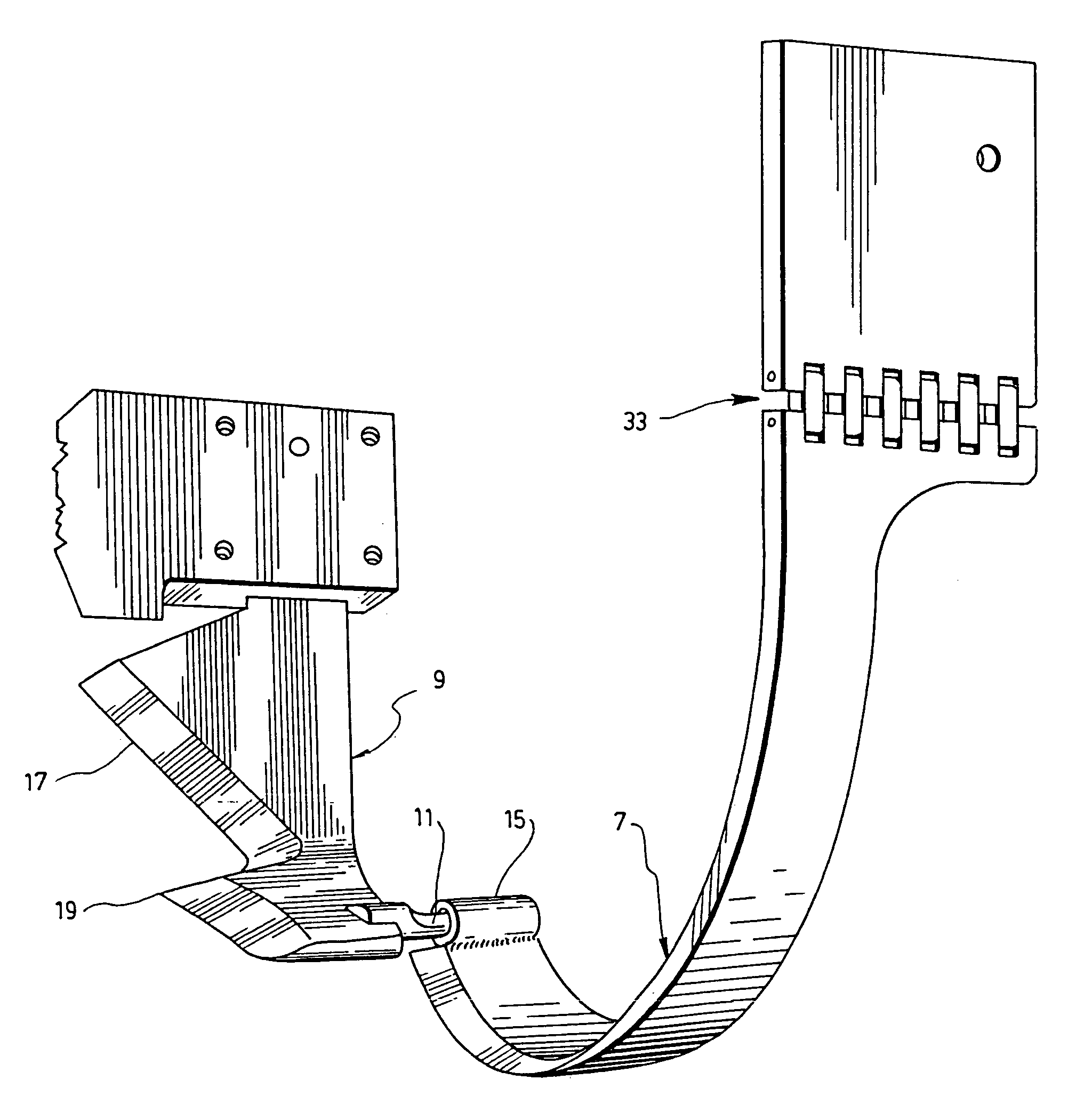
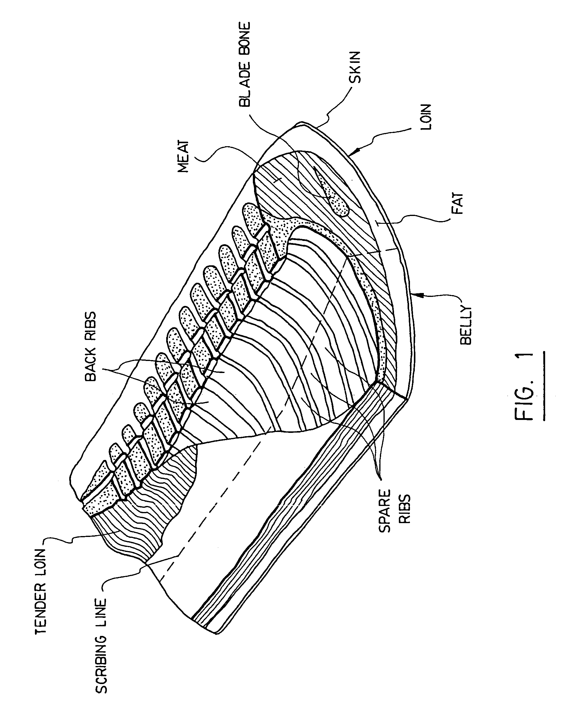
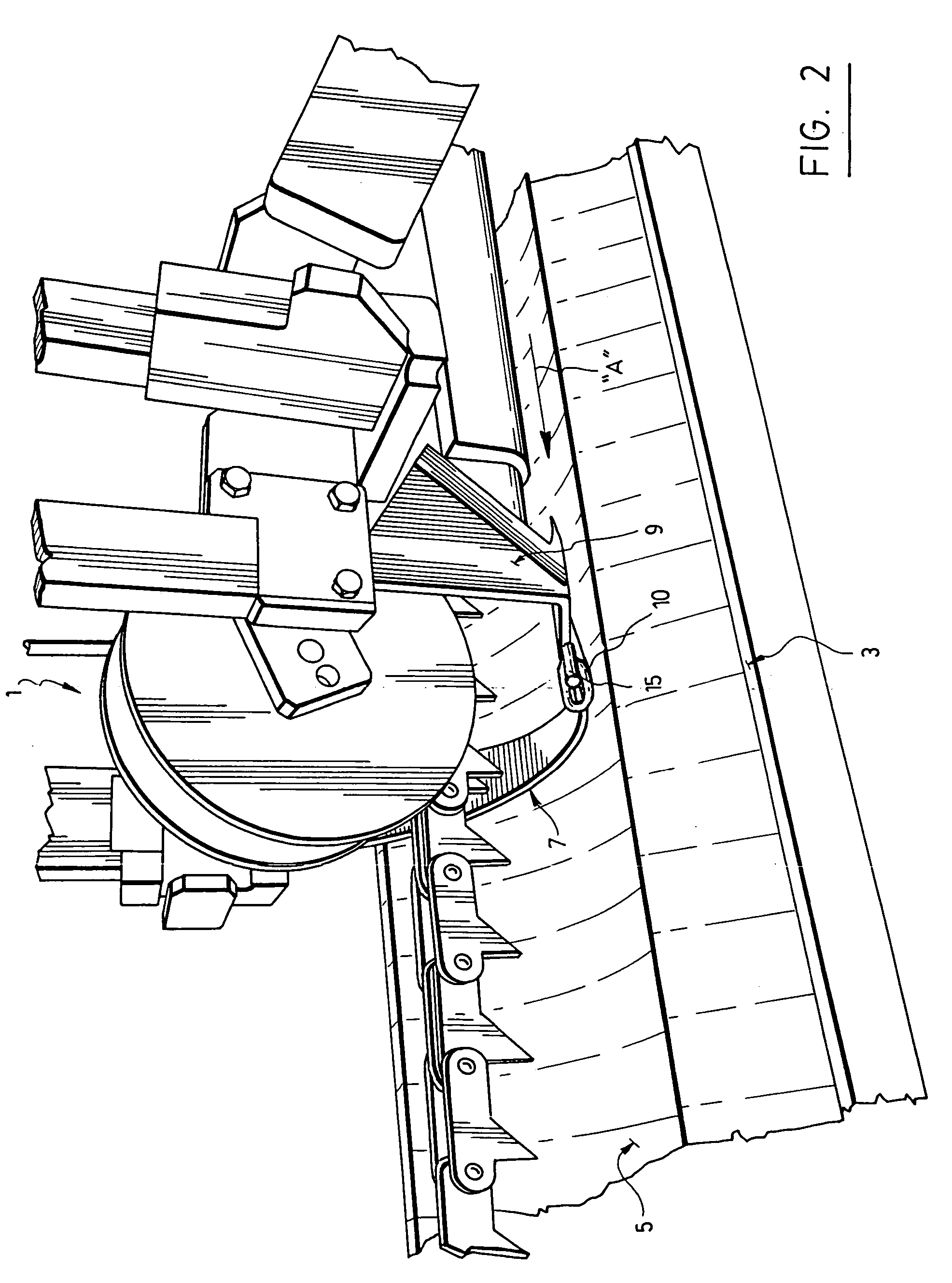
[0050]The improved loin puller1 according to the different preferred embodiments of the invention as shown in FIGS. 2 to 6, is devised for trimming off the fat and skin viz. the “backfat”, from the back of a loin “L” scribed from a belly “B”, as shown in FIG. 1. This improved loin puller 1 basically comprises:[0051]a frame 3;[0052]a conveying system 5 mounted onto the frame for engaging the loin and moving it towards a cutting zone in the direction shown by the arrow “A” in the drawings; and[0053]a cutting tool mounted onto the frame 3 in the cutting zone for engaging the loin when the same is moved by the conveying system 5 and for cutting the backfat to be trimmed off from the same with the so cut backfat still remaining attached to the adjacent part of the belly, as is shown in FIGS. 4 and 6

[0054]As aforesaid, the improvement essentially lies in that the cutting tool comprises two blades 7 and 9. One of these blades, namely the one numbered 7, is arcuate and positioned onto the f...


PUM


Abstract

Disclosed is a loin puller for trimming off the backfat of a loin that has been scribed from a belly. This loin puller has a frame on which is mounted a conveying system for engaging the loin and moving it towards a cutting zone. In this zone, a cutting tool is mounted for engaging the loin when it is moved by the conveying system, and for cutting the backfat to be trimmed off from the loin, with the so-cut backfat remaining attached to the belly. The cutting tool has two blades that are preferably controlled independently from each other. One of these blades is arcuate and positioned onto the frame so as to engage at least one part of the loin from a side of the loin opposite to the belly, and to cut the backfat to be trimmed from the loin. The other blade is L-shaped and positioned onto the frame so as to engage another part of the loin and cut the backfat to be trimmed thereof directly from the scribing line just below the back ribs of the loin. The two blades are long enough to ensure that all the backfat of the loin be trimmed off. Advantageously, the arcuate blade has one end pivotably attached to the frame by a joint and another opposite end attached either to the frame or the L-shaped blade. The use of such a joint gives much more flexibility of the arcuate blade and makes it much more efficient.

Description

CROSS REFERENCE[0001]The present application is a continuation-in-part of application Ser. No. 11 / 074,795 filed on Mar. 9, 2005 now U.S. Pat. No. 7,214,129 with the benefit of the priority of Canadian patent application No. 2,460,547 filed on Mar. 10, 2004.FIELD OF THE INVENTION[0002]The present invention relates to a loin puller of improved structure, which comprises a cutting tool having two blades instead of one only, in order to trim off the backfat from a loin while leaving the so cut backfat attached to the belly.BACKGROUND OF THE INVENTION[0003]Loin pullers are well known machines used in the meat processing industry for trimming off the backfat of a loin, in particular a pork loin.[0004]As shown in FIG. 1 of the accompanying drawings, the central part or “middle” of the carcass-half of a piece of meat comprises two main parts respectively called “loin” and “belly”. The loin is adjacent to the cut portion of the spinal column. The front portion of the loin contains ribs which...

Claims


Application Information

Patent Timeline
Patent Type & Authority Patents(United States)
IPC IPC(8): A22C18/00
CPCA22B5/0005A22C17/0046
Inventor ROY, JEAN-GUYDUFOUR, YVON
Owner G E LEBLANC INC
Learn More