Stents with proximal and distal end elevations

a proximal and distal end elevation technology, applied in the field of stents, can solve the problems of self-fixation characteristics, risk of local axial displacement of the stent, and the inability of the stent to resist flattening, and achieve the effect of less shortening the stent and being manufactured easier

Inactive Publication Date: 2008-02-19
BOSTON SCI CORP
View PDF71 Cites 23 Cited by
  • Summary
  • Abstract
  • Description
  • Claims
  • Application Information

AI Technical Summary

Benefits of technology

[0009]It is therefore an object of the present invention to improve a less-shortening stent such that it can be used universally, and more specifically in moving and / or in curved body passageways avoiding migration and flattening deformation thereof. A further object of the invention is to provide a stent which can be manufactured easier.
[0010]The term “elevation” has the meaning of an impression or bulge of the stent wall as well in the negative as in the positive sense, i.e. extending inwardly or outwardly of the tubular stent wall. Accordingly, the tubular wall has at least a local inwardly and / or outwardly formed elevation, whereby the wires are plastically deformed in a way that the number of degrees of freedom for their movement within the braiding is reduced. This means that the mesh cells defined by the braided wires are “frozen” by a reduced capability of the wires to rotate and shift relative to each other at their crossing points. The braided tubular wall retains its less-shortening feature and becomes more stable against radial deformation. A further advantage of the formed elevations is the possibility to make a short stent of the type mentioned in the introduction. Such stents are usually cut from the braiding blank and comprise an unwanted conical shape due to a memory effect from the braiding process. This shape can be converted into a cylindrical tube and conserved by forming elevations on the stent wall.
[0012]More dense distribution of the elevations at the proximal and distal ends of the stent will provide higher stability at these areas for better anchoring thereof with the tissue of the body vessel. This embodiment is preferred if the stent is to be implanted in ostium positions for a safe fixation of the stent ends in order to prevent migration of the stent and disturbing for example the blood flow into a side branch through this ostium. Another preferred application of such a stent is the support of a vessel having a hard plaque stenosis whereby the stent comprises a higher density of elevations in the stenotic region.
[0013]In a preferred embodiment of the invention the elevations are formed outwardly so that they can serve as an anchor against stent migration by engaging into the inner vessel wall to be supported. Moreover, the deployment of such a stent with delivery devices as known in the art is enhanced since the retraction of the outer sheath is easier. This results from a reduced friction between the inside of the delivery sheath and the radially outwardly pressing stent touching the sheath only at the elevations.
[0014]In another preferred embodiment of the present invention the local elevations have an elongate shape which makes the manufacturing of such stents very easy by using wires to emboss the tubular wall. The elevations may have an arched cross-sectional shape. Preferably the height of the elevations are approximately one to two times the wire diameter of the braid.
[0015]These embossments or elevations can be formed in patterns helically on the tubular wall, where in a preferred embodiment the helical elevation pattern has a different pitch than the wires of the braid in order to deform as many wires as possible. The elevations may also be formed annularly or in an axial direction on the tubular wall depending on the desired effect. Where the elevations are placed annularly the stent wall comprises an improved radial stability, whereas elevations in axial directions impart to the stent a higher longitudinal stability which is especially useful for implantation in the airways.

Problems solved by technology

A consequence of the lower radial force is a reduction of the self-fixation characteristics with the risk of a local axial displacement of the stent within the body passageway.
Moreover, the stent is not stable enough to resist flattening if it is implanted in arched vessels.
But the less-shortening stent segment still has not sufficient shape stability for use in curved areas of body vessels.
In addition, it is to be said that the used manufacturing methods are quite expensive.

Method used


Image

  • Stents with proximal and distal end elevations
  • Stents with proximal and distal end elevations
  • Stents with proximal and distal end elevations

Examples


Embodiment Construction

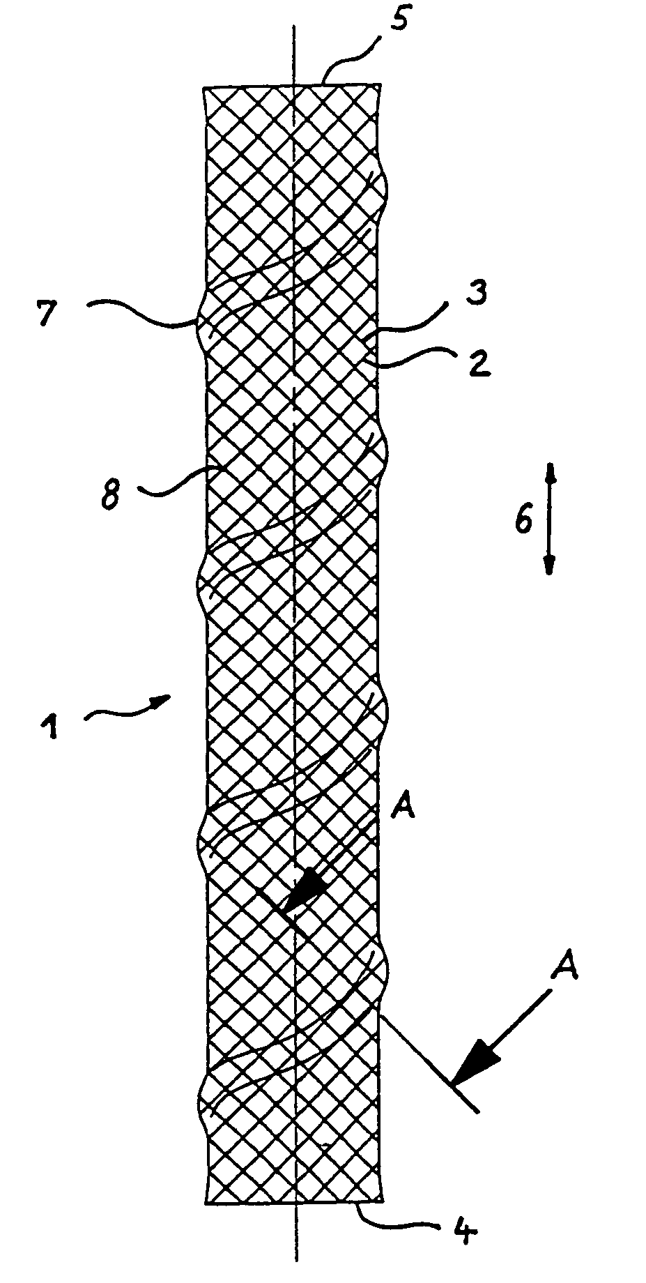
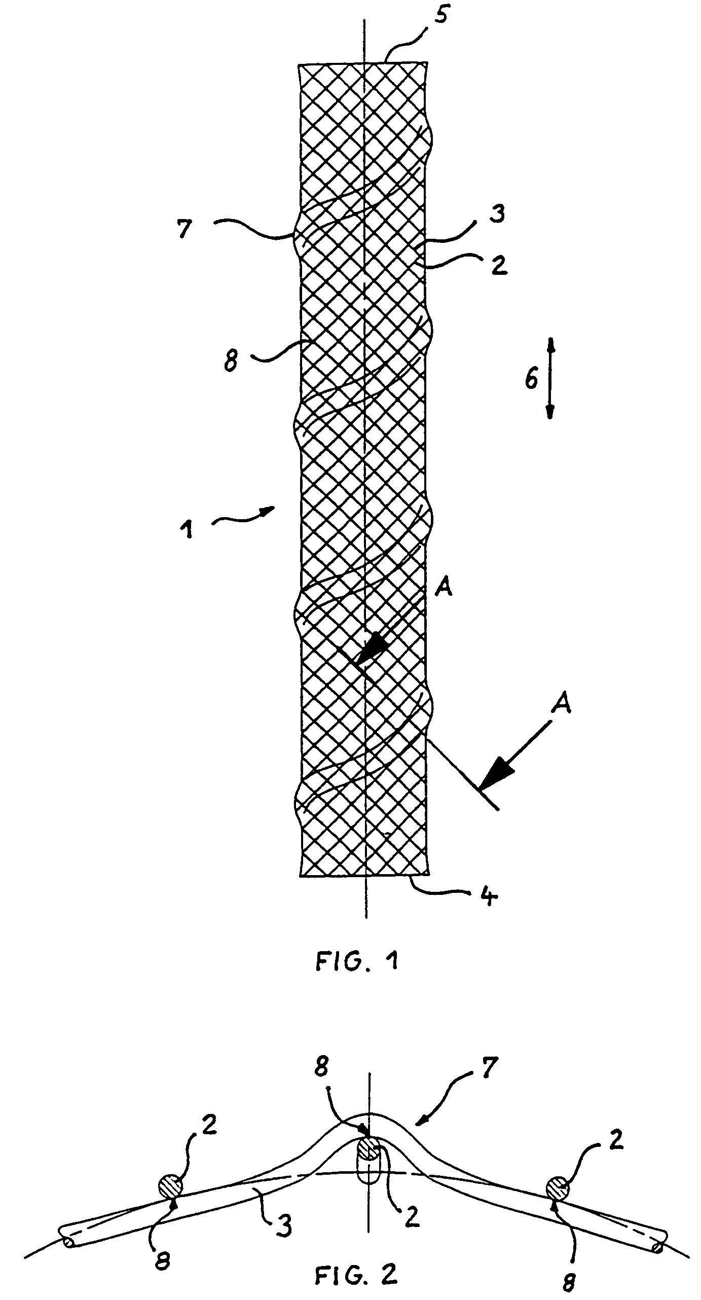
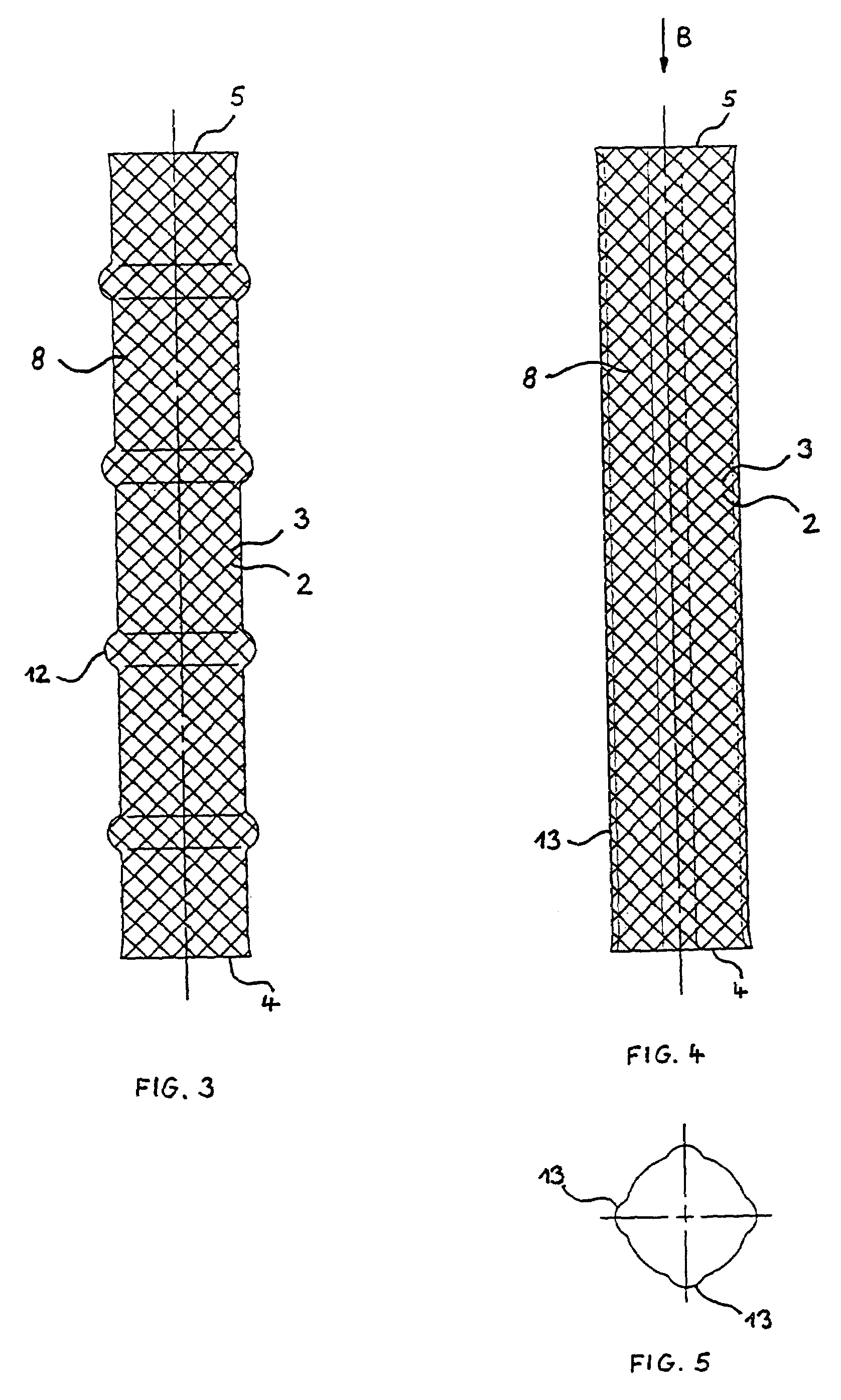
[0028]The stent depicted in FIG. 1 comprises a flexible self-expanding braided tubular wall 1 which is composed of a first plurality of parallel spring stainless steel wires 2 helically wound in a first direction crossing a second plurality of parallel spring stainless steel wires 3 helically wound in a second direction opposite to the first one. The braided structure assures contraction of the stent in the radial direction when the proximal and distal ends 4 and 5 of the stent are pulled away from one another as exemplified by arrows 6, and self-expansion of the stent in the radial direction when the pull according to arrows 6 is released. This configuration is well known in the art and needs no further explanation. Of course, other known braidings or patterns providing the same effect may be used.

[0029]The tubular wall 1 of the stent having a helical pattern of elevations 7 which is outwardly formed and has an angle of gradient or pitch slightly smaller than the angle of gradient ...


PUM

PropertyMeasurementUnit
anglesaaaaaaaaaa
braiding angleaaaaaaaaaa

Abstract

A prosthetic stent with a tubular wall having local inwardly or outwardly formed elevations. Stents having such elevations have a higher mechanical stability if bent according to the curvature of the body vessels to be supported or repaired. Also a method for manufacturing a stent with such elevations is described.

Description

[0001]This is a divisional of prior application Ser. No. 09 / 874,609, (now U.S. Pat. No. 6,652,577), filed Jun. 5, 2001 as a divisional of application Ser. No. 09 / 431,988 (now U.S. Pat. No. 6,240,978), filed Nov. 2, 1999 as a divisional of application Ser. No. 08 / 993,033 (now U.S. Pat. No. 5,993,483), filed Dec. 18, 1997.BACKGROUND OF THE INVENTION[0002]This application claims priority under 35 U.S.C. § 119 of European Patent Application No. 97202152.1, filed in the European Patent Office on Jul. 17, 1997.[0003]The present invention relates to a stent for use in a body passageway, comprising a flexible self-expanding braided tubular wall being composed of helically wound wires and having proximal and distal ends. The invention also relates to a method for manufacturing such a stent.[0004]A stent of the type as mentioned in the introduction is described for example in U.S. Pat. No. 4,655,771. The tubular wall is composed of several flexible thread elements each of which extends along ...

Claims


Application Information

Patent Timeline
Patent Type & Authority Patents(United States)
IPC IPC(8): A61F2/06A61F2/00A61F2/88A61F2/90
CPCA61F2/90D04C1/06D04C3/48A61F2/88A61F2002/3011D10B2509/06Y10T29/49874A61F2230/0002D10B2403/0241
Inventor GIANOTTI, MARC
Owner BOSTON SCI CORP
Why Eureka
Try Eureka