Braided stent

a brad stent and stent technology, applied in the field of brad stents, can solve the problems of insufficient shape stability of less-shortening stent segments, the risk of local axial displacement of stents, and the inability of stents to resist flattening, so as to achieve less-shortening stents and facilitate manufacturing.

Inactive Publication Date: 2007-05-31
BOSTON SCI CORP
View PDF59 Cites 71 Cited by
  • Summary
  • Abstract
  • Description
  • Claims
  • Application Information

AI Technical Summary

Benefits of technology

[0008] It is therefore an object of the present invention to improve a less-shortening stent such that it can be used universally, and more specifically in moving and / or in curved body passageways avoiding migration and flattening deformation thereof. A further object of the invention is to provide a stent which can be manufactured easier.

Problems solved by technology

A consequence of the lower radial force is a reduction of the self fixation characteristics with the risk of a local axial displacement of the stent within the body passageway.
Moreover, the stent is not stable enough to resist flattening if it is implanted in arched vessels.
But the less-shortening stent segment still has not sufficient shape stability for use in curved areas of body vessels.
In addition, it is to be said that the used manufacturing methods are quite expensive.

Method used


Image

  • Braided stent
  • Braided stent
  • Braided stent

Examples


Embodiment Construction

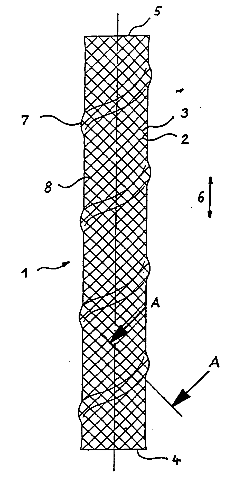
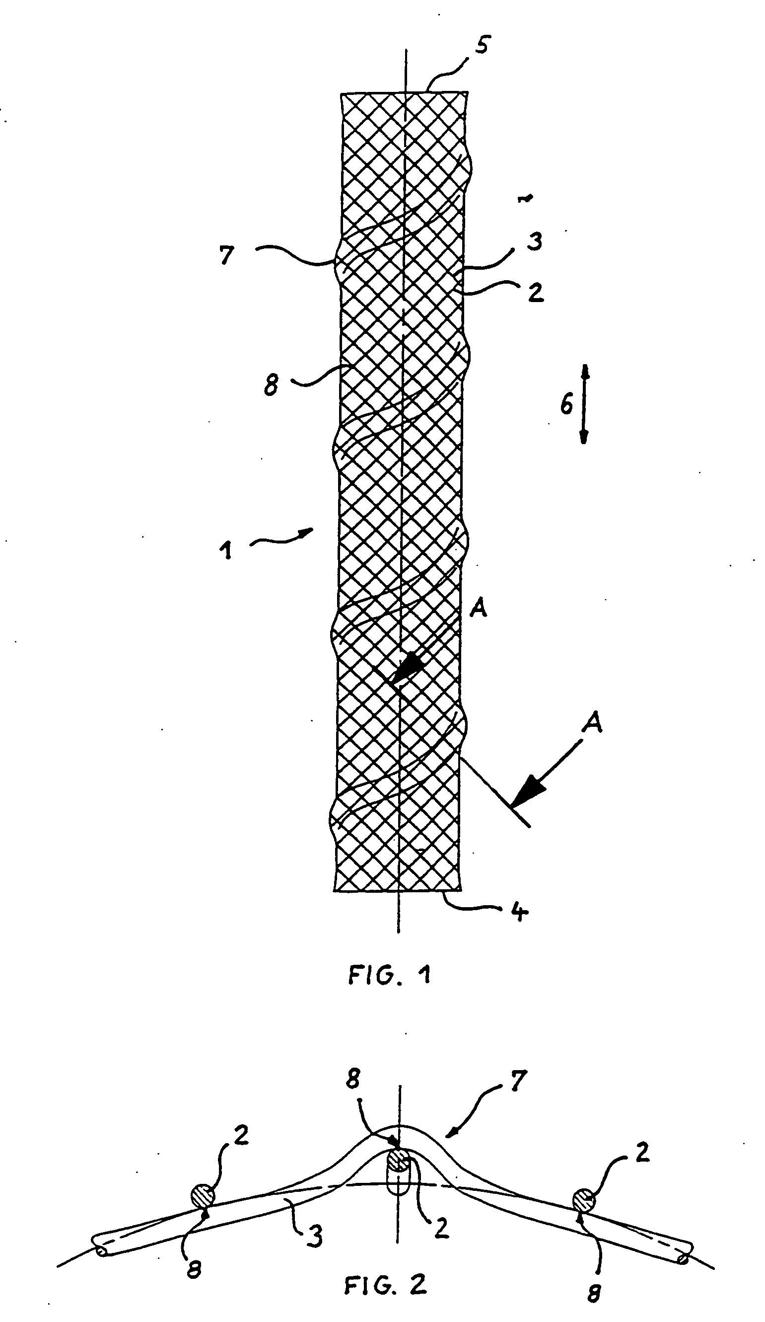
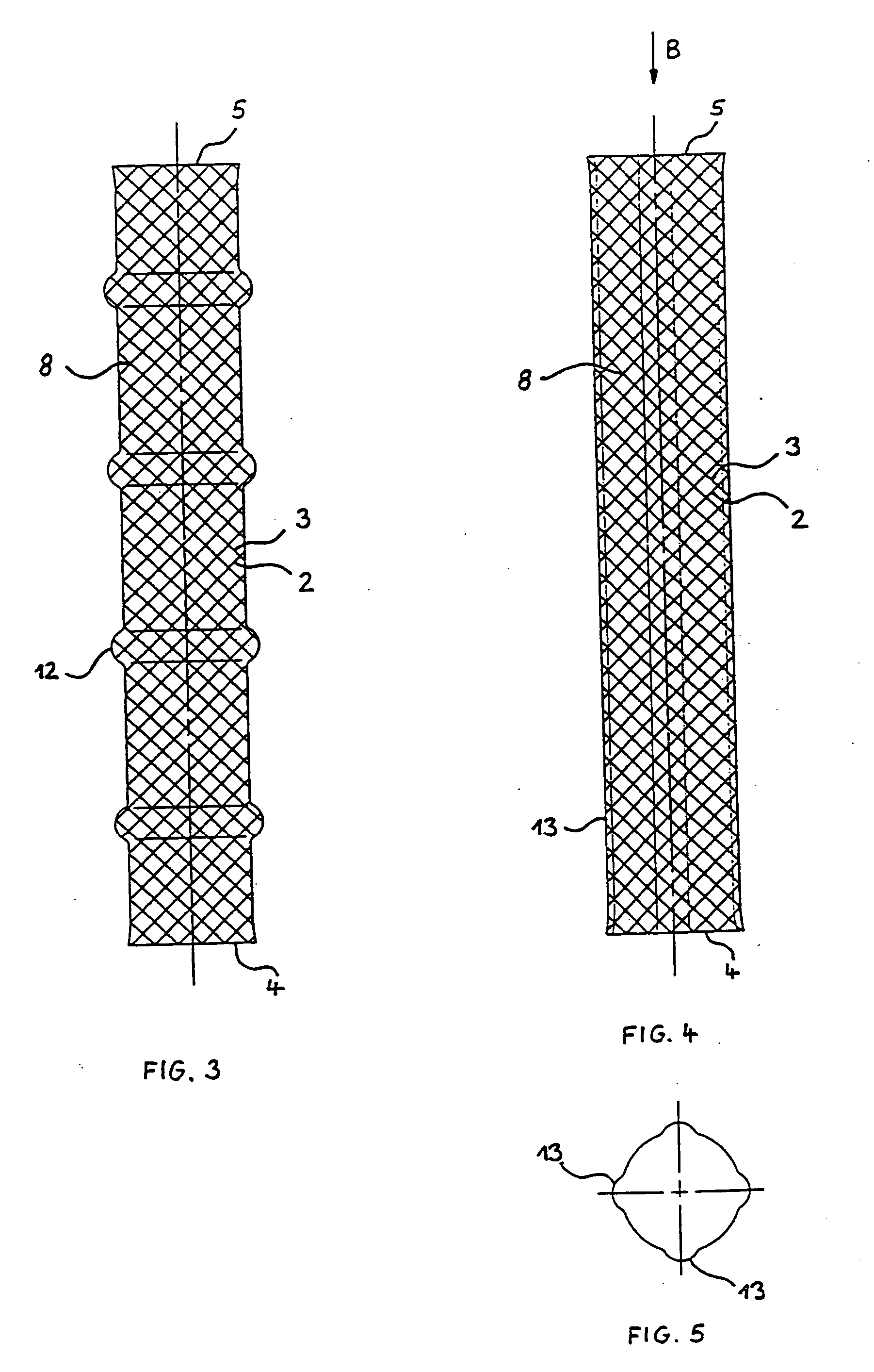
[0027] The stent depicted in FIG. 1 comprises a flexible self expanding braided tubular wall 1 which is composed of a first plurality of parallel spring stainless steel wires 2 helically wound in a first direction crossing a second plurality of parallel spring stainless steel wires 3 helically wound in a second direction opposite to the first one. The braided structure assures contraction of the stent in the radial direction when the proximal and distal ends 4 and 5 of the stent are pulled away from one another as exemplified by arrows 6, and self expansion of the stent in the radial direction when the pull according to arrows 6 is released. This configuration is well known in the art and needs no further explanation. Of course, other known braidings or patterns providing the same effect may be used.

[0028] The tubular wall 1 of the stent having a helical pattern of elevations 7 which is outwardly formed and has an angle of gradient or pitch slightly smaller than the angle of gradie...


PUM

PropertyMeasurementUnit
obtuse anglesaaaaaaaaaa
anglesaaaaaaaaaa
braiding angleaaaaaaaaaa

Abstract

A stent for use in a body passageway includes a plurality of wires braided to form a self-expanding braided tubular structure. The braided wires form braiding angles along a length of the tubular structure. A portion of the wires are plastically deformed to reduce foreshortening of the braided structure.

Description

CROSS-REFERENCE TO RELATED APPLICATIONS [0001] This application is a continuation of application Ser. No. 10 / 674,729, filed Sep. 30, 2003, which is a divisional of application Ser. No. 09 / 874,609, filed Jun. 5, 2001, now U.S. Pat. No. 6,652,577, which is a divisional of application Ser. No. 09 / 431,988, filed Nov. 2, 1999, now U.S. Pat. No. 6,240,978, which is a divisional of application Ser. No. 08 / 993,033, filed Dec. 18, 1997, now U.S. Pat. No. 5,993,483, which claims the benefit of European Patent Application No. 97202152.1, filed in the European Patent Office on Jul. 17, 1997, the contents of all of which are incorporated herein by reference.BACKGROUND OF THE INVENTION [0002] The present invention relates to a stent for use in a body passageway, comprising a flexible self-expanding braided tubular wall being composed of helically wound wires and having proximal and distal ends. The invention also relates to a method for manufacturing such a stent. [0003] A stent of the type as me...

Claims


Application Information

Patent Timeline
Patent Type & Authority Applications(United States)
IPC IPC(8): A61F2/06A61F2/00A61F2/88A61F2/90
CPCA61F2/88A61F2/90A61F2002/3011D10B2509/06Y10T29/49874D04C1/06D04C3/48A61F2230/0002D10B2403/0241
Inventor GIANOTTI, MARC
Owner BOSTON SCI CORP
Why Eureka
Try Eureka